
This page holds Class 10 Science Chapter 12, Magnetic Effects of Electric Current — 13 printed pages (NCERT pp. 195–207) from the official NCERT textbook.
The official chapter PDF is right here, and below the download you will find a plain-language map of every section, figure and exercise in the chapter.
The chapter answers one question first: what does an electric current do to a compass? It then follows the field from a straight wire to a loop to a solenoid, introduces the force on a wire in a field, and ends with the safe wiring of a house.
Get the Official Chapter 12 PDF
The complete chapter, with all its activities, both worked examples and every exercise question, is published free by NCERT on its official site.
Open the NCERT Class 10 Science Chapter 12 Magnetic Effects of Electric Current PDF to read the chapter exactly as printed — the same section headings, figures and questions you will be examined from.
Chapter at a Glance
The table below shows how much this chapter holds. Every figure and question in it is unpacked further down the page.
| What the chapter contains | Count |
|---|---|
| Printed pages (NCERT pp. 195–207) | 13 |
| Sections | 8 |
| Activities (12.1–12.7) | 7 |
| Figures | 14 |
| Worked examples | 2 |
| Exercise questions | 9 |
| In-text questions | 12 |
Read as one movement, the chapter does four things. It establishes that a current creates a magnetic field, then maps that field for a straight wire, a circular loop and a solenoid (pp. 198–201).
It then introduces the force a magnetic field exerts on a current-carrying conductor (pp. 202–203), and closes with the safety wiring of a house — live, neutral and earth wires, parallel connections and the fuse (pp. 204–205).
What This Chapter Covers, Section by Section
If you are stuck on one part, jump straight to it. This map gives the printed page for every section of the chapter, each described in a sentence or two.
| Section | Printed pages | What it teaches |
|---|---|---|
| Opening + Activity 12.1 | 195 | A compass needle deflects when current flows through a nearby wire — electricity and magnetism are linked (Oersted, 1820). |
| 12.1 Magnetic field and field lines | 196–197 | Defines the magnetic field; iron filings and a compass trace field lines around a bar magnet. |
| 12.2 Magnetic field from a current-carrying conductor | 198–201 | Concentric circular field lines around a straight wire; the right-hand thumb rule; the circular loop and the n-turn coil; the solenoid and the electromagnet. |
| 12.3 Force on a current-carrying conductor in a magnetic field | 202–203 | A rod in a magnetic field is pushed sideways; Fleming’s left-hand rule; force is largest when current is perpendicular to the field. |
| 12.4 Domestic electric circuits | 204–205 | Live, neutral and earth wires; parallel wiring; the fuse; short-circuiting and overloading. |
The chapter opens with the scientist who started it all. Hans Christian Oersted (1777–1851) discovered in 1820 that a compass needle deflected when an electric current passed through a nearby wire — the first proof that electricity and magnetism were related.
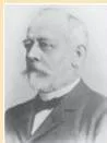
That one accidental observation is the engine of the whole chapter. Every idea below is either a consequence of it or a use of it.
This is a chapter best learned by doing. Each activity below demonstrates one key observation, and the table pairs it with the page it is on.
| Activity | Page | What it demonstrates |
|---|---|---|
| 12.1 | 195 | A compass needle deflects when current passes through a nearby wire. |
| 12.2 | 196 | Iron filings align along the field lines around a bar magnet. |
| 12.3 | 196 | A compass traces out one field line at a time; deflection increases near the poles. |
| 12.4 | 198 | Reversing the current reverses the deflection of the needle. |
| 12.5 | 198 | Iron filings show concentric circular field lines around a straight wire. |
| 12.6 | 201 | Iron filings show the field pattern of a circular coil. |
| 12.7 | 202 | A current-carrying rod in a magnetic field is displaced sideways. |
Key Concepts: The Ideas This Chapter Builds
This section is the working core of the chapter. The five ideas below are what every direction question and every safety question in it uses — each with the textbook page so you can check the book’s own words at the same time.
Magnetic Fields and Field Lines
A magnetic field is the region around a magnet in which the force of the magnet can be detected (NCERT p.196). Field lines are the drawing of that region: the lines along which iron filings align, or along which a compass needle moves (p.197).
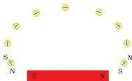
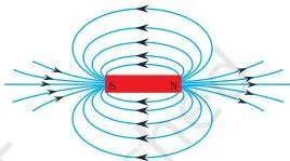
Figure 12.3 shows how one field line is drawn step by step (p.197). Place a compass near the north pole of the magnet, mark the two ends of the needle, then move the compass so its south pole sits where its north pole was. Joining the marks gives a smooth curve — one field line.
The chapter gives four properties of field lines (p.197). Learn to state all four in your own words:
- Direction — a field line points where the north pole of a compass needle would move.
- Emergence — outside the magnet, lines leave the north pole and merge at the south pole; inside the magnet they run from south to north.
- Strength — the closer the lines, the stronger the field; crowding at the poles shows the field is strongest there.
- No crossing — two lines never intersect, because a compass would have to point two ways at once.
Why learn these as a list? The chapter’s own question asks you to list the properties of magnetic field lines (p.200) — these four, in your own words, are the complete answer.
The Right-Hand Thumb Rule
Before any field-direction problem, you need the picture: the field lines around a straight current-carrying wire are concentric circles centred on the wire (p.198). This is the pattern Activity 12.5 shows with iron filings.
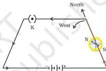
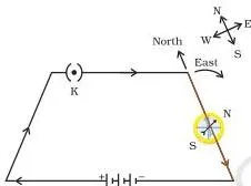
Activity 12.4 gives the key observation first (p.198): place the wire parallel to and over a compass needle, pass the current, and the needle deflects. Reverse the current and the needle deflects the opposite way — so the field direction follows the current direction.
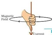
The right-hand thumb rule converts that observation into a method (p.199–200): hold the wire in your right hand with your thumb pointing along the current; your fingers wrap around the conductor in the direction of the field lines. The book adds that this rule is also called Maxwell’s corkscrew rule (p.200).
Try it once. A wire carries current straight up: thumb points north, and the curled fingers show the field circling counterclockwise when seen from above. At a point east of the wire the field points north; at a point west of it, south.
Two facts from Activity 12.5 you will need for magnitude: the field gets stronger as the current increases, and weaker as you move away from the wire (p.198–199).
Keep this warning for later: the right-hand thumb rule gives a field direction around a wire. A force direction needs your left hand and the rule two sections below.
Circular Loop and Solenoid
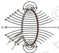
Bend the straight wire into a circle and the same field appears in a new shape. At the centre of a circular loop, the large concentric arcs around each section of wire look like straight lines, and every section contributes field lines in the same direction inside the loop (p.200).
Coil it up and the field multiplies: a circular coil of n turns produces a field n times as large as a single turn, because the field of each turn adds to the others (p.200).
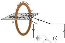
Activity 12.6 shows the iron-filing pattern around a current-carrying circular coil (Fig 12.9, p.201) — the same straight lines through the middle that an in-text question asks about.
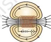
A solenoid is a coil of many circular turns of insulated copper wire wrapped closely in the shape of a cylinder (p.201). Its outside field matches a bar magnet: one end behaves as a north pole and the other as a south pole.
Inside, the field lines are parallel straight lines, so the field is uniform — the same at all points (p.201).
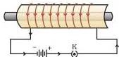
Slide a piece of soft iron inside the coil and the coil becomes an electromagnet (Fig 12.11, p.201) — the chapter’s practical application of everything so far.
Fleming’s Left-Hand Rule
A current-carrying conductor placed in a magnetic field feels a force — the field pushes the wire. Activity 12.7 shows an aluminium rod suspended between the poles of a horseshoe magnet, with the field directed upwards, being pushed sideways when current flows through it (p.202).
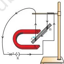
In the activity the rod moves left; reverse the current and it moves right, reverse the field and it moves right again (p.202). The force direction depends on both the current and the field.
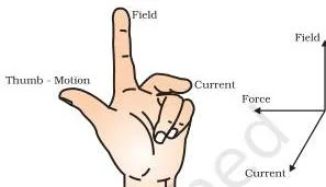
The force is largest when the current is at right angles to the magnetic field (p.202). In that perpendicular case, use Fleming’s left-hand rule: stretch the thumb, first finger and second finger of your left hand so all three are mutually perpendicular. First finger — magnetic field; second finger — current; thumb — force or motion (p.202–203).
Devices that run on this force include the electric motor, electric generator, loudspeakers, microphones and measuring instruments (p.202).
Electron warning: conventional current runs opposite to the motion of electrons. Example 12.2 (p.203) does exactly this — reverse the electron direction, then apply Fleming’s rule; that is why the force on the electron in that example is into the page.
Domestic Circuits and Safety
This is the chapter’s real-world finish: the wiring that brings 220 V into a house, and the devices that keep it safe.
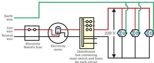
Three wires do the job (p.204):
- Live wire (red insulation) carries the supply; it sits at 220 V with respect to the neutral.
- Neutral wire (black insulation) is the return path.
- Earth wire (green insulation) connects to a metal plate buried deep in the ground — the safety wire.
The earth wire protects appliances with metallic bodies — electric press, toaster, table fan, refrigerator. If current leaks to the metal body, the earth wire gives the leakage a low-resistance path and keeps the body’s potential at the earth’s, so the user does not receive a severe shock (p.204).
Appliances are connected in parallel across the live and neutral wires so that each appliance gets the same potential difference (p.204–205). Often the house has two circuits: a 15 A circuit for high-power appliances such as geysers and air coolers, and a 5 A circuit for bulbs and fans (p.204).
Two dangers share one defence (p.205). Short-circuiting happens when live and neutral come into direct contact — through damaged insulation or a fault in an appliance — and the current abruptly increases. Overloading can also come from an accidental hike in the supply voltage, or from plugging too many appliances into a single socket.
The electric fuse is the defence: the Joule heating of the high current melts the fuse and breaks the circuit before the wiring or the appliances are damaged (p.204–205). The principle of the fuse itself comes from Section 11.7 of the previous chapter, Electricity — p.204 of this chapter says so.
Here is the calculation the chapter’s own questions use, with original numbers. A 1.5 kW electric iron runs on a 220 V domestic circuit fitted with a 5 A fuse.
Step 1: Convert the power rating to watts: \( P = 1.5\ \text{kW} = 1500\ \text{W} \).
The supply is \( V = 220\ \text{V} \) and the circuit is rated \( 5\ \text{A} \).
Step 2: Use \( P = VI \) to find the current the iron draws.
\[ I = \frac{P}{V} = \frac{1500}{220} \approx 6.8\ \text{A} \]
Conclusion: The iron draws about 6.8 A — more than the 5 A rating — so the circuit is overloaded. The fuse melts and breaks the circuit before the high current damages the wiring or the iron (NCERT p.205). This is exactly why a high-power appliance like this is placed on the 15 A circuit instead.
Most direction questions in this chapter reduce to one choice: are you finding a field or a force? The table settles it.
| You are finding… | Rule | Hand | How to apply it |
|---|---|---|---|
| Direction of the magnetic field around a current-carrying wire | Right-hand thumb rule | Right | Thumb points along the current; curled fingers give the field direction (p.199–200). |
| Direction of the force on a current-carrying conductor in a magnetic field | Fleming’s left-hand rule | Left | First finger — field, second finger — current, thumb — force (p.202–203). |
Figure Walkthrough: Reading the Diagrams in the Chapter
The drawing questions in this chapter ask for exactly these diagrams. Read each one feature by feature here, and you will be able to reproduce it when asked.
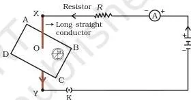
Figure 12.1 is the founding observation (p.195). The copper wire XY runs perpendicular to the page, with a small compass beside it. At rest the needle lies along the north-south direction; once the key is closed and current flows, the needle deflects. That deflection — current produces a magnetic field — is the chapter’s whole subject in one image.
Figure 12.4 is the bar magnet’s field, revealed by iron filings in Activity 12.2 and traced by a compass in Activity 12.3 (p.196–197). Read the arrows: field lines emerge from the north pole and merge at the south pole — by convention, the direction a free north pole would move (p.197).
Two details are easy to miss. The lines crowd at the poles, showing the field is strongest there. And inside the magnet the lines run south to north, which is what makes them closed curves (p.197).
Figure 12.7 is the grip itself (p.200). Hold a pen upright in your right hand: thumb along the pen is the current, and the fingers wrapped around it curl in the direction of the field lines. The fingers tell you which way the concentric circles go.
Figure 12.8 shows the field of a circular loop (p.200). The important feature is the middle: at the centre of the loop, the large arcs around each section of wire appear as straight lines, and every section contributes field in the same direction. So the field through the centre points one way, perpendicular to the plane of the loop.
Figure 12.10 is the solenoid (p.201). Put it beside Fig 12.4 above and the two match: on the outside, the solenoid’s field pattern is exactly a bar magnet’s — one end north, one end south. Inside, the field lines are parallel straight lines: that is the uniform field, the same at all points.
Figure 12.13 is Fleming’s left-hand rule (p.203). The three fingers are mutually perpendicular: first finger — magnetic field, second finger — current, thumb — force or motion. Point the first two along the directions you know and the thumb lands on the answer.
Figure 12.15 is a common domestic circuit (p.205). Trace it from left to right: the supply enters the electricity meter, passes the main fuse and the main switch, then branches into separate circuits.
Every appliance sits across the live and neutral wires with its own switch, and the earth wire connects to the metallic body of each appliance. The parallel arrangement is why every appliance receives the same 220 V.
Key Terms and Definitions from Chapter 12
Use this table as a lookup: meet an unfamiliar term in the chapter, find it here, and read the plain definition plus the page where the book introduces it.
| Term | Plain definition | NCERT page |
|---|---|---|
| Magnetic field | The region around a magnet in which the force of the magnet can be detected. | 196 |
| Magnetic field lines | The lines along which iron filings or a compass needle align — the map of the magnetic field. | 197 |
| Right-hand thumb rule | Hold the wire with your right hand, thumb along the current; fingers curl in the direction of the field lines. Also called Maxwell’s corkscrew rule. | 199–200 |
| Solenoid | A coil of many circular turns of insulated copper wire wrapped closely in the shape of a cylinder. | 201 |
| Electromagnet | A soft iron core magnetised by placing it inside a current-carrying solenoid. | 201 |
| Fleming’s left-hand rule | With thumb, first and second fingers of the left hand mutually perpendicular: first finger = field, second finger = current, thumb = force. | 202–203 |
| Live wire | The supply wire with red insulation, at 220 V with respect to the neutral. | 204 |
| Neutral wire | The supply wire with black insulation — the return path. | 204 |
| Earth wire | The safety wire with green insulation, connected to a metal plate buried deep in the earth. | 204 |
| Electric fuse | A safety device that melts by Joule heating and breaks the circuit when the current is too high. | 204–205 |
| Short-circuiting | When live and neutral wires come into direct contact, making the current rise abruptly. | 205 |
| Overloading | Excess current in a circuit, caused by a voltage hike or by too many appliances on one socket. | 205 |
Common Mistakes in This Chapter (and How to Fix Them)
These are the errors that make students lose marks on this chapter — named before you make them. Each row pairs the mistake with the correction and a way to check your answer.
| Mistake | Correct rule | How to check your answer |
|---|---|---|
| Drawing field lines that stop at the magnet’s surface | Field lines are closed curves: outside the magnet they run north to south, and inside they continue from south to north (p.197). | Trace any line in your drawing through the magnet — it must form a closed loop. |
| Drawing two field lines crossing | They can never cross: at the crossing point a compass would have to point two ways at once (p.197). | Check that no two lines share any point. |
| Reading field strength from line length | Strength is shown by crowding (closeness) of the lines, not by how long they are (p.197). | Compare line spacing: denser lines mean a stronger field. |
| Using the right-hand thumb rule where Fleming’s left-hand rule is needed | The right hand gives the field around a wire; the LEFT hand gives the force on a wire (p.199–200 vs p.202–203). | Ask: am I finding a field or a force? Field → right hand; force → left hand. |
| Applying Fleming’s rule to an electron without reversing direction | For an electron beam, current is taken opposite to the electron motion (p.203). | Reverse the electron direction first, then apply the rule — as Example 12.2 does. |
| Calling the green wire live | Green is the earth wire — the safety wire. Live is red, neutral is black (p.204). | Memorise red = live, black = neutral, green = earth (tested in Exercise Q3(b), p.207). |
The one-line memory that fixes half this table: right hand for the field around the wire, left hand for the force on the wire.
How the Chapter’s Exercises Test These Ideas
The chapter’s exercises test a small set of skills. If you know which skill you are weak at, jump to the question that practises it. This maps the book’s own exercises; it is not a prediction about any examination.
| Skill | Questions in the chapter | What a full answer includes |
|---|---|---|
| Recognising the field around a straight wire | Exercise Q1 (p.207) | Choose (d) — the field consists of concentric circles centred on the wire, as Activity 12.5 showed. |
| Choosing and stating a rule | Exercise Q7 (p.207) | Name each rule: right-hand thumb rule for the field around a straight wire; Fleming’s left-hand rule for the force on a wire in a perpendicular field. Part (iii), about the current induced in a rotating coil, points to electromagnetic induction — an idea this chapter’s sections do not develop. |
| Applying the right-hand rule to a loop | In-text Q1 (p.200) | For a clockwise current seen from above, curl the right-hand fingers clockwise; the thumb points into the table — the field inside the loop. Outside the loop, the field comes back out. |
| Force on a moving charge | In-text Q1 (p.203); Exercise Q6 (p.207) | Use Fleming’s left-hand rule. For an electron beam, reverse the motion to get the current direction before applying the rule. |
| What a magnetic field changes about a proton | In-text Q1 (p.203) | The field pushes sideways, changing direction: velocity and momentum change; mass and speed do not. |
| True/false on the coil and the green wire | Exercise Q3 (p.207) | (a) True — the field at the centre of a long circular coil is parallel straight lines; (b) False — green is the earth wire, not the live wire. |
| Explaining short circuit and earth wire | Exercise Q8, Q9 (p.207) | Q8: live and neutral touch, so current rises abruptly (p.205). Q9: the earth wire gives leakage current a low-resistance path and keeps metallic bodies at earth potential (p.204). |
| Power, current and the fuse calculation | In-text Q2 (p.205) | \( I = \frac{2000}{220} \approx 9.1\ \text{A} \) — more than the 5 A rating, so the circuit is overloaded and the fuse blows to protect it. |
A three-step recipe for any direction question:
- List every direction the question gives you — current, field, motion.
- Decide what you are finding: a field (right hand) or a force (left hand).
- If the moving charge is an electron, reverse its motion before treating it as current.
What to Remember from This Chapter
The chapter closes with its own summary (p.206). Here it is as a checklist, in plainer words — run through it and you have the chapter.
- A compass needle is a small bar magnet; the end that points north is the north pole.
- A magnetic field is the region around a magnet in which the force of the magnet can be detected (p.196).
- Field lines map the field: direction is where a north pole would move, crowding shows strength, and lines never cross (p.197).
- A current-carrying wire produces a field of concentric circles whose direction is given by the right-hand thumb rule (p.199–200).
- The shape of the conductor shapes the field; a solenoid’s field matches a bar magnet’s, with a uniform field inside (p.201).
- An electromagnet is a soft iron core wound with a coil of insulated copper wire (p.201).
- A current-carrying conductor in a magnetic field feels a force — largest when current and field are perpendicular — given by Fleming’s left-hand rule (p.202–203).
- Household supply in India is 220 V AC at 50 Hz, with live (red), neutral (black) and earth (green) wires, and appliances in parallel (p.204, p.206).
- The fuse protects circuits from short-circuiting and overloading (p.204–205).
Related Chapters and Resources
This listing is maintained for the 2026-27 academic session using the NCERT textbook information available to us. NCERT remains the authority for confirming the latest edition.
This chapter builds directly on the previous one, Electricity: the fuse is carried over from Section 11.7 of that chapter, as p.204 of this one notes. Revise the two back to back.
- Class 10 Science notes and chapters — the full set of Science chapters for revision.
- Electricity (Chapter 11) — the previous chapter, where the fuse is first explained.
- Our Environment (Chapter 13) — the chapter that follows this one in the book.
- Class 10 study hub — every subject in one place.
- CBSE notes index — all classes and subjects.
For the complete book in one place, the official NCERT Class 10 Science textbook page on ncert.nic.in carries every chapter’s PDF. The chapter file itself is linked at the top of this page.
Sources and Data Verification
This page describes Chapter 12 of the NCERT Class 10 Science textbook, official NCERT edition on ncert.nic.in. Page references here follow the printed NCERT pages 195–207.
This page covers this one chapter of the book. It does not cover the chapters around it — Electricity (Chapter 11) and Our Environment (Chapter 13) are linked above for that.
The listing is maintained for the current academic session. Textbook contents and the examinable syllabus are not always identical — check the current official CBSE syllabus before planning revision.
NCERT settles the textbook content, editions and PDFs; CBSE settles the curriculum, syllabus and examinations.
| What the chapter holds | Count | Where it is used |
|---|---|---|
| Printed pages | 13 | |
| Sections in the chapter | 8 | |
| Figures with NCERT captions | 14 | |
| Worked examples | 2 | solved step by step in our NCERT Solutions |
| Exercise questions | 9 | answered in our NCERT Solutions |
| In-text questions | 12 | |
| Activities | 7 | |
| Official NCERT PDF | Download the chapter PDF | the chapter exactly as NCERT publishes it |
Reference: NCERT Class 10 Science textbook, chapter 12, official edition on ncert.nic.in.
Frequently Asked Questions
Why does a compass needle deflect when an electric current flows through a nearby wire?
The current in the wire produces a magnetic field around it. The compass needle is a small bar magnet, so the field exerts a force on it and it deflects (p.195). This was the observation that linked electricity and magnetism.
What is the difference between the right-hand thumb rule and Fleming’s left-hand rule?
They answer different questions. The right-hand thumb rule (p.199–200) finds the direction of the magnetic field around a current-carrying wire: thumb along the current, fingers giving the field. Fleming’s left-hand rule (p.202–203) finds the direction of force on a wire in a magnetic field: first finger field, second finger current, thumb force.
Right hand for a field, left hand for a force.
Is the magnetic field the same at all points inside a solenoid?
Yes. Inside a solenoid the field lines are parallel straight lines, which means the field is uniform — the same at all points inside (p.201).
Why is the earth wire green and what does it protect us from?
The earth wire has green insulation and is connected to a metal plate buried deep in the ground (p.204). It is a safety wire: for appliances with metallic bodies it gives any leakage current a low-resistance path, keeping the body at earth’s potential so the user does not get a severe shock.
What is a short circuit and how does an electric fuse protect the circuit?
A short circuit occurs when the live and neutral wires come into direct contact — damaged insulation or a fault in an appliance — making the current rise abruptly (p.205). The fuse protects the circuit through Joule heating: the high current melts the fuse, which breaks the circuit and stops the unduly high current (p.205).
Why can two magnetic field lines never cross each other?
Because at the crossing point a compass needle would have to point in two directions at once, which is impossible (p.197).
Explore Class 10 Science Books
Related chapters:
- Chemical Reactions and Equations
- Acids, Bases and Salts
- Metals and Non-metals