
This page gives you Chapter 11, Electricity, from the NCERT Class 10 Science textbook — the chapter runs 24 printed pages, from page 171 to page 194 of the book.
The official PDF of the chapter is right here at the top, and below it a section-by-section guide to what the chapter teaches: the key formulas, the figures, the activities, and the mistakes students make in it.
Get the official NCERT Electricity chapter PDF
Open the Electricity Class 10 Science Chapter 11 NCERT PDF to get the chapter exactly as printed in the book — the same pages of text, figures, activities and exercise questions, ready to read on screen or print.
The file is hosted on ncert.nic.in, the official portal of the National Council of Educational Research and Training, so this version is always the current official edition.
Chapter at a glance: what the NCERT file contains
The table below lists how much the chapter holds — its sections, figures, worked examples and exercise questions — so you know what to expect before you open the PDF.
The chapter follows one logical line: electric current and potential difference, then circuit diagrams, then Ohm’s law, then the factors that decide resistance, then series and parallel combinations, then the heating effect of current, and finally electric power.
What Chapter 11 teaches, section by section
Use this map to jump to any topic in your book within seconds.
| NCERT section | Printed page | What it teaches |
|---|---|---|
| 11.1 Electric current and circuit | p. 172 | Defines current as the rate of flow of charge; introduces the coulomb, the ampere and the ammeter. |
| 11.2 Electric potential and potential difference | pp. 173–174 | Explains what makes charge flow, defines the volt and introduces the voltmeter. |
| 11.3 Circuit diagram | pp. 174–175 | Shows the standard symbols used to draw circuits, summarised in Table 11.1. |
| 11.4 Ohm’s law | pp. 175–180 | Builds the law \( V \propto I \) through activities; defines resistance and resistivity. |
| 11.6 Resistance of a system of resistors | pp. 181–187 | Derives the equivalent resistance of series and parallel combinations. |
| 11.7 Heating effect of electric current | pp. 188–190 | Derives \( H = VIt = I^2Rt \) and looks at bulbs, heating devices and fuses. |
| 11.8 Electric power | pp. 191–192 | Defines power and the kilowatt hour used in electricity bills. |
The chapter closes with a “What you have learnt” summary on page 192 and a full set of exercises on pages 193–194.
Key concepts of Electricity, explained simply
Electricity is the flow of charge. The chapter asks four questions in order: what makes charge flow, what resists the flow, how resistors combine, and what the flow produces. Answer those four and you have the whole chapter.
Electric current and the ampere
Current tells you how much charge is moving — the amount that crosses any point of the circuit each second (NCERT, p. 172). If a charge \( Q \) crosses a cross-section in time \( t \), the current is \[ I = \frac{Q}{t} \]
- Coulomb (C) is the SI unit of charge — the charge carried by nearly \( 6 \times 10^{18} \) electrons. One electron carries \( 1.6 \times 10^{-19}\ \text{C} \).
- Ampere (A) is the SI unit of current: \( 1\ \text{A} = 1\ \text{C/s} \). Small currents use \( 1\ \text{mA} = 10^{-3}\ \text{A} \) and \( 1\ \mu\text{A} = 10^{-6}\ \text{A} \).
- The ammeter, which measures current, is always connected in series, because it must count every charge that flows.
- Direction: current is conventionally taken from the positive terminal to the negative terminal outside the cell — opposite to the drift of electrons. The convention was fixed before electrons were discovered.
Because each electron carries \( 1.6 \times 10^{-19}\ \text{C} \), the number of electrons in one coulomb is \( 1/(1.6 \times 10^{-19}) \approx 6.25 \times 10^{18} \) — which is why NCERT says one coulomb is “nearly \( 6 \times 10^{18} \) electrons”.
Worked example (new numbers).
A current of 2 A flows through a wire for 5 minutes.
How much charge passes?
Step 1: Convert the time to seconds: \( t = 5\ \text{min} = 300\ \text{s} \).
\[ Q = It = 2\ \text{A} \times 300\ \text{s} = 600\ \text{C} \]
Final answer: 600 C of charge flows past any point of the circuit.
Potential difference and the volt
Charges do not flow by themselves. They flow only when two points of a conductor are at different electric pressure — the potential difference — the way water flows only when one end of a pipe is higher than the other (NCERT, p. 173).
Potential difference is the work done per unit charge in moving charge from one point to the other:
\[ V = \frac{W}{Q} \]
- Volt (V) is the SI unit: \( 1\ \text{V} = 1\ \text{J/C} \). One volt moves one coulomb of charge with one joule of work.
- The voltmeter is always connected in parallel across the two points being compared.
- A cell maintains the potential difference by chemical action; its chemical energy is spent to keep the current flowing.
Worked example (new numbers).
How much work is done in moving a charge of 3 C across two points having a potential difference of 4 V?
\[ W = VQ = 4\ \text{V} \times 3\ \text{C} = 12\ \text{J} \]
Final answer: 12 J of work is done.
Ohm’s law and resistance
Ohm’s law is the chapter’s central rule: double the voltage across a metallic conductor and the current doubles too — provided its temperature stays the same.
\[ V \propto I \quad \text{so} \quad \frac{V}{I} = R \quad \text{and} \quad V = IR \]
- The constant \( R \) is the resistance — the property of a conductor that resists the flow of charge (NCERT, p. 176). Its SI unit is the ohm (\( \Omega \)): \( 1\ \Omega = 1\ \text{V/A} \).
- The constant-temperature condition is exam-critical: the V-I graph is a straight line through the origin only while the temperature does not change.
- A rheostat is a variable resistance used to regulate the current without changing the voltage source (p. 176).
- Activity 11.1 (p. 175) establishes the law: with 1, 2, 3 and 4 cells across the same nichrome wire, the ratio \( V/I \) stays nearly constant.
Note the rearranged form \( I = V/R \): for a fixed resistance, a smaller voltage gives a proportionally smaller current.
Resistivity: what resistance depends on
Resistance belongs to one particular wire. Resistivity belongs to the material — the same for every wire of copper, whatever its size.
Activity 11.3 (pp. 177–178) isolates three variables: doubling the length halves the current, a thicker wire increases the current, and changing the material changes the current. So resistance depends on length, cross-sectional area and the nature of the material:
\[ R = \rho \frac{l}{A} \]
- Resistivity \( \rho \) is the constant of proportionality, measured in ohm metre (\( \Omega\ \text{m} \)); it is a characteristic property of the material (p. 178).
- Both resistance and resistivity change with temperature.
- Table 11.2 (p. 178) ranks materials: silver and copper have the lowest resistivity (best conductors); glass, rubber and ebonite have resistivity up to \( 10^{17}\ \Omega\ \text{m} \) (insulators); alloys sit in between, nichrome around \( 100 \times 10^{-6}\ \Omega\ \text{m} \).
- Alloys do not oxidise readily at high temperatures — that is why heating coils are made of alloys, and tungsten, which has a very high melting point, is used for bulb filaments (p. 190).
Resistors in series
In series, the current has exactly one path. Whatever current leaves the battery must pass through every resistor, one after another (NCERT, p. 181).
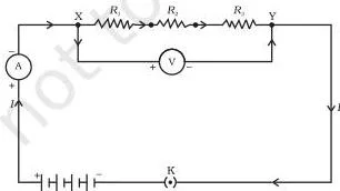
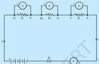
The figure shows three resistors joined end to end in a single loop. Activity 11.4 (p. 182) proves the current is the same through every resistor — the ammeter reads the same value anywhere in the loop. Activity 11.5 (p. 183) proves the voltages add:
\[ V = V_1 + V_2 + V_3 \]
Applying Ohm’s law to the whole combination and to each resistor separately gives the series rule (NCERT, p. 184):
\[ R_s = R_1 + R_2 + R_3 \]
The equivalent resistance of a series combination is greater than any individual resistor.
Worked example (new numbers).
A 2 \( \Omega \), a 5 \( \Omega \) and an 8 \( \Omega \) resistor are joined in series with a 9 V battery.
Find the total resistance and the current.
Step 1: Series rule: \( R_s = 2 + 5 + 8 = 15\ \Omega \).
\[ I = \frac{V}{R_s} = \frac{9\ \text{V}}{15\ \Omega} = 0.6\ \text{A} \]
Final answer: total resistance 15 Ω; the same current of 0.6 A flows through every resistor. This is why one fused bulb breaks a string of fairy lights (NCERT, p. 187).
Resistors in parallel
In parallel, the current is given several separate paths between the same two points, like water sharing several pipes that join again (NCERT, p. 181).
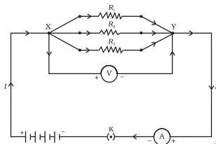
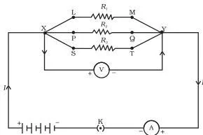
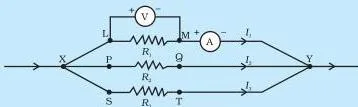
The figure shows three resistors connected between the same two points X and Y. Activity 11.6 (p. 185) shows the potential difference is the same across every branch, and the total current is the sum of the branch currents (p. 186):
\[ I = I_1 + I_2 + I_3 \]
Applying Ohm’s law to each branch gives the parallel rule (NCERT, p. 186):
\[ \frac{1}{R_p} = \frac{1}{R_1} + \frac{1}{R_2} + \frac{1}{R_3} \]
The equivalent resistance of a parallel combination is smaller than the smallest individual resistor — more paths means less overall resistance.
Worked example (new numbers).
A 12 V battery is connected across a parallel pair of 6 \( \Omega \) and 12 \( \Omega \).
Find each branch current and the equivalent resistance.
Step 1: Each branch sees the full 12 V, so \( I_1 = 12/6 = 2\ \text{A} \) and \( I_2 = 12/12 = 1\ \text{A} \).
\[ I = I_1 + I_2 = 2 + 1 = 3\ \text{A} \]
\[ \frac{1}{R_p} = \frac{1}{6} + \frac{1}{12} = \frac{3}{12} \quad \Rightarrow \quad R_p = 4\ \Omega \]
Final answer: branch currents 2 A and 1 A, total current 3 A, equivalent resistance 4 Ω — smaller than the 6 Ω branch.
Combined worked example (new numbers).
A 4 \( \Omega \) resistor is in series with a parallel pair of 6 \( \Omega \) and 12 \( \Omega \), across a 12 V battery.
Find the total resistance and the total current.
- Step 1: The parallel pair gives \( R_p = 4\ \Omega \) (as above).
- Step 2: Add the series resistor: \( R_{total} = 4 + 4 = 8\ \Omega \).
\[ I = \frac{12\ \text{V}}{8\ \Omega} = 1.5\ \text{A} \]
Check: the 4 Ω series resistor drops \( 1.5 \times 4 = 6\ \text{V} \), so the pair gets \( 12 – 6 = 6\ \text{V} \); the branch currents \( 6/6 = 1\ \text{A} \) and \( 6/12 = 0.5\ \text{A} \) add to 1.5 A.
Consistent.
Final answer: total resistance 8 Ω, total current 1.5 A.
This is why domestic wiring is parallel (p. 187): every appliance gets the same voltage and keeps working independently when others are switched off or fail.
Series or parallel: choosing the right connection
The fastest way to confuse two circuits is to forget which quantity stays the same in each. This table fixes it (NCERT, p. 187).
| Quantity | Series | Parallel |
|---|---|---|
| Current | One current through every resistor | Splits: \( I = I_1 + I_2 + I_3 \) |
| Potential difference | Adds: \( V = V_1 + V_2 + V_3 \) | Same across every branch |
| Equivalent resistance | \( R_s = R_1 + R_2 + R_3 \); greater than the largest | \( 1/R_p = 1/R_1 + 1/R_2 + 1/R_3 \); smaller than the smallest |
| Failure behaviour | One failure breaks the whole circuit | Other branches keep working |
| Typical use | Where a single path is wanted, e.g. fairy lights | Domestic wiring |
Takeaway: household circuits are parallel because every device needs its rated voltage and must keep working when others are switched off (NCERT, p. 187).
Joule’s law of heating
A resistor that carries current gets hot. Joule’s law tells you exactly how much heat it produces.
The source supplies energy \( VQ \) while a charge \( Q \) moves through a potential difference \( V \). In a purely resistive circuit, all of that energy appears as heat (NCERT, p. 188):
\[ H = VIt \]
Using Ohm’s law \( V = IR \) turns this into Joule’s law (NCERT, p. 189):
\[ H = I^2Rt \]
- Heat is proportional to the square of the current, to the resistance, and to the time.
- Practical order: when a device is connected to a known voltage, find \( I = V/R \) first, then use \( H = I^2Rt \).
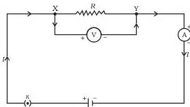
The figure shows a battery supplying a steady current to a resistor: every joule of electrical energy supplied ends up as heat in the resistor.
Worked example (new numbers).
A 5 \( \Omega \) resistor carries a steady current of 2 A for 10 minutes.
How much heat is produced?
Step 1: Time in seconds: \( t = 10\ \text{min} = 600\ \text{s} \).
\[ H = I^2Rt = (2\ \text{A})^2 \times 5\ \Omega \times 600\ \text{s} = 12000\ \text{J} \]
Final answer: 12,000 J of heat, or 12 kJ.
Electric power and the kilowatt hour
Power tells you how fast a device uses energy; the electricity bill charges you for the total energy used, which is power multiplied by time.
Electric power is the rate of consumption of energy (NCERT, p. 191):
\[ P = VI = I^2R = \frac{V^2}{R} \]
- Watt (W) is the SI unit: \( 1\ \text{W} = 1\ \text{V} \times 1\ \text{A} \).
- The watt is small, so bills use the kilowatt: \( 1\ \text{kW} = 1000\ \text{W} \).
- Energy \( = \) power \( \times \) time; the commercial unit is the kilowatt hour: \( 1\ \text{kW h} = 3.6 \times 10^6\ \text{J} \) (p. 191).
- NCERT’s “More to Know” note (p. 191): electrons are not consumed in a circuit — you pay the board for the energy used to move them, which is why bills are in kilowatt hours.
Cost example (new numbers).
A 2000 W appliance runs 2 hours a day for 30 days.
What energy does it consume, and what is the cost at Rs 5 per unit?
Step 1: Energy in watt hours: \( 2000\ \text{W} \times 2\ \text{h/day} \times 30\ \text{days} = 120000\ \text{W h} \).
\[ \frac{120000\ \text{W h}}{1000} = 120\ \text{kW h} \]
Step 2: Cost at Rs 5 per kilowatt hour.
\[ \text{Cost} = 120 \times 5 = 600\ \text{rupees} \]
Final answer: 120 kW h of energy, costing Rs 600.
What the chapter’s activities prove
These six activities are how the chapter builds its laws from observation rather than assertion. Each one changes one thing in a circuit and reads what happens.
| Activity | NCERT page | What it measures | Conclusion |
|---|---|---|---|
| 11.1 | p. 175 | V and I for 1, 2, 3, 4 cells | \( V/I \) stays nearly constant — Ohm’s law |
| 11.2 | p. 176 | Current through nichrome wire, torch bulb, 10 W bulb | Different components have different resistance |
| 11.3 | pp. 177–178 | Current for wires of length \( l \) and \( 2l \), a thick wire, and a copper wire | \( R \propto l \), \( R \propto 1/A \), and material matters |
| 11.4 | p. 182 | Ammeter reading at different points of a series loop | Same current everywhere in series |
| 11.5 | p. 183 | \( V \), \( V_1 \), \( V_2 \), \( V_3 \) across series resistors | \( V = V_1 + V_2 + V_3 \) |
| 11.6 | p. 185 | \( I \), \( I_1 \), \( I_2 \), \( I_3 \) in parallel branches | \( I = I_1 + I_2 + I_3 \) |
Reading the NCERT circuit figures
Circuit diagrams are the chapter’s visual language. Every figure below uses the same set of symbols — cell, switch, ammeter, voltmeter, resistor — so learn those once and the physics of each figure becomes obvious.
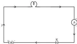
This is the basic circuit of the whole chapter: a cell, an electric bulb, an ammeter and a plug key in one closed loop. Read the current path from the positive terminal of the cell, through the bulb and ammeter, back to the negative terminal.
The one thing students misread here is the ammeter: it sits on the main path, in series, because it must count every charge that flows.
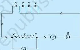
This is the Ohm’s law experiment (Activity 11.1). A nichrome wire XY sits in the circuit; the ammeter in series measures the current through it, while the voltmeter in parallel across the wire measures the potential difference between its ends. Changing the number of cells changes V, and the ratio V/I stays constant — that is Ohm’s law.
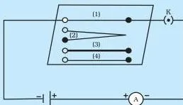
This circuit tests what resistance depends on (Activity 11.3). The same gap XY accepts different wires one at a time: length \( l \), length \( 2l \), a thicker wire of length \( l \), and a copper wire of length \( l \). Swapping wires while watching the ammeter isolates one variable at a time — length, then thickness, then material.
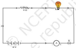
This is the circuit of Example 11.7: a 6 V battery, a 20 \( \Omega \) lamp and a 4 \( \Omega \) resistor in series. Reading it explains the numbers: total resistance \( 20 + 4 = 24\ \Omega \), current \( 6/24 = 0.25\ \text{A} \), so the lamp drops 5 V and the resistor 1 V.
The chapter also prints a V-I graph as Fig. 11.3 (p. 175): a straight line through the origin for a nichrome wire — as \( I \) increases, \( V \) increases linearly. The slope of the line equals the resistance. Exercise question 7 (p. 193) gives you a table of V and I values and asks you to plot this graph and calculate the resistance from the slope.
Definitions and formulas: a quick reference
Learn the three core equations — \( I = Q/t \), \( V = W/Q \) and \( V = IR \) — and derive the rest of the chapter from them.
| Quantity | What it means (one line) | SI unit | Page |
|---|---|---|---|
| Electric charge | The amount of electricity transferred | coulomb (C) | p. 172 |
| Electric current | Rate of flow of charge, \( I = Q/t \) | ampere (A) | p. 172 |
| Potential difference | Work done per unit charge, \( V = W/Q \) | volt (V) | p. 173 |
| Resistance | The ratio \( V/I \); how strongly the conductor resists current | ohm (\( \Omega \)) | p. 176 |
| Resistivity | A characteristic property of the material, \( \rho = RA/l \) | ohm metre (\( \Omega\ \text{m} \)) | p. 178 |
| Electric power | Rate of consumption of energy, \( P = VI \) | watt (W) | p. 191 |
| Electrical energy | The commercial unit of energy used on bills | kilowatt hour (kW h) | p. 191 |
| Formula | What the symbols mean | Page |
|---|---|---|
| \( I = \dfrac{Q}{t} \) | current = charge ÷ time | p. 172 |
| \( V = \dfrac{W}{Q} \) | potential difference = work ÷ charge | p. 173 |
| \( V = IR \) | Ohm’s law: voltage = current × resistance | p. 176 |
| \( R = \rho \dfrac{l}{A} \) | resistance from length, area and material | p. 178 |
| \( R_s = R_1 + R_2 + R_3 \) | equivalent resistance in series | p. 184 |
| \( \dfrac{1}{R_p} = \dfrac{1}{R_1} + \dfrac{1}{R_2} + \dfrac{1}{R_3} \) | equivalent resistance in parallel | p. 186 |
| \( H = I^2Rt \) | Joule’s law of heating | p. 189 |
| \( P = VI = I^2R = \dfrac{V^2}{R} \) | electric power in three forms | p. 191 |
| \( 1\ \text{kW h} = 3.6 \times 10^6\ \text{J} \) | kilowatt hour in joules | p. 191 |
Common mistakes in Electricity, and the correct idea
Most errors in this chapter are sign, unit and connection errors, not physics errors. Each row below names the mistake, the correct rule, and a way to check yourself.
| Mistake | Correct rule | How to check your answer |
|---|---|---|
| Drawing current along the electron direction | Current flows from positive to negative outside the cell — opposite to electrons (p. 172) | Mark the + terminal; current leaves from there. |
| Swapping the instruments | Ammeter in series; voltmeter in parallel (pp. 172–173) | Trace the loop: ammeter on the main path, voltmeter bridging the two points. |
| Assuming R changes when V changes | For a given resistor at constant temperature R is fixed; halving V halves I (p. 176) | Find \( R = V/I \) once and reuse it for the new V. |
| Adding parallel resistances like series | Use reciprocals; the equivalent is smaller than the smallest resistor (p. 186) | Check your answer is less than every branch resistance. |
| Wiring the house in series | Parallel: same voltage for all devices; one failure does not stop others (p. 187) | Ask: if one bulb fails, must all stop? Series → yes, parallel → no. |
| Confusing kW with kWh | kW is power; kWh is energy. The bill charges per unit, the kWh (p. 191) | A bill is energy = power × time, so the unit carries h. |
| Thinking electrons are consumed | The cell supplies energy but does not use up charges (p. 191) | A circuit keeps working for years — charges circulate. |
Exam notes: how to practise this chapter
This chapter is built so each formula feeds the next; practise the formulas in the same order the book builds them.
- Start with \( I = Q/t \), then \( V = W/Q \), then \( V = IR \).
- Add \( R = \rho l/A \) with diameter-to-area conversions.
- Do the two combination rules — series first, then parallel.
- Finish with heat \( H = I^2Rt \) and power \( P = VI \).
The chapter-end exercise set is the natural practice bank. Map each question to the idea it tests before solving:
- Q1 — a cut wire joined in parallel: equivalent resistance.
- Q2, Q3 — the terms for power; the bulb rated 220 V, 100 W on 110 V.
- Q6 — \( R = \rho l/A \) from diameter; resistance after doubling the diameter.
- Q7 — plotting the V-I graph; the slope gives resistance.
- Q8, Q9 — Ohm’s law; current through the 12 \( \Omega \) resistor in a series circuit.
- Q10–Q13 — parallel and combined circuits.
- Q14–Q16 — comparing power and energy.
- Q17 — rate of heating (this is power).
- Q18 — the explain items: tungsten, alloys, series vs parallel, area, transmission wires.
Unit traps: convert minutes to seconds, mA to A (2.5 mA = \( 2.5 \times 10^{-3}\ \text{A} \)), hours to seconds where heat is asked, and convert diameter to area using \( \pi d^2/4 \) (p. 180).
Syllabus note: textbook contents and the examinable syllabus are not always identical — check the current official CBSE syllabus for what is examinable this session.
Revision summary: the chapter in one page
This is the chapter’s own closing summary (“What you have learnt”, p. 192) rephrased. Revise it once, then use the exercise map above to test yourself.
- Current is the rate of flow of charge, \( I = Q/t \); conventionally it flows opposite to the electrons (p. 172).
- The SI unit of current is the ampere (p. 172).
- Potential difference is measured in volts; \( V = W/Q \) (p. 173).
- Resistance, in ohms, controls the magnitude of the current (p. 176).
- Ohm’s law: \( V \propto I \) at constant temperature (p. 176).
- Resistance depends on length, area and material: \( R = \rho l/A \) (p. 178).
- Series: \( R_s = R_1 + R_2 + R_3 \) (p. 184).
- Parallel: \( 1/R_p = 1/R_1 + 1/R_2 + 1/R_3 \) (p. 186).
- Heat in a resistor: \( H = VIt = I^2Rt \) (pp. 188–189).
- Power \( P = VI = I^2R = V^2/R \) in watts; the commercial unit of energy is the kilowatt hour: \( 1\ \text{kW h} = 3.6 \times 10^6\ \text{J} \) (pp. 191–192).
Related resources for Class 10 Science
This listing is maintained for the 2026-27 academic session using the NCERT textbook information available to us. NCERT remains the authority for confirming the latest edition.
For every chapter of this book, see the Class 10 Science notes. The previous chapter, The Human Eye and the Colourful World, and the next chapter, Magnetic Effects of Electric Current, sit on either side of Electricity in the textbook.
The Class 10 hub collects notes across subjects, and the CBSE notes home lists every class.
For the official text, use the Electricity Class 10 Science Chapter 11 NCERT PDF and the NCERT textbook portal — both hosted on ncert.nic.in.
| What the chapter holds | Count | Where it is used |
|---|---|---|
| Printed pages | 24 | |
| Sections in the chapter | 11 | |
| Figures with NCERT captions | 10 | |
| Tables | 4 | |
| Worked examples | 13 | solved step by step in our NCERT Solutions |
| Exercise questions | 18 | answered in our NCERT Solutions |
| In-text questions | 23 | |
| Activities | 6 | |
| Official NCERT PDF | Download the chapter PDF | the chapter exactly as NCERT publishes it |
Reference: NCERT Class 10 Science textbook, chapter 11, official edition on ncert.nic.in.
Sources and data verification
- The section, figure and question references on this page come from the current NCERT Class 10 Science textbook, chapter 11, as published on ncert.nic.in.
- This page covers that one chapter of that book; it does not describe other editions or other books.
- It is maintained for the current academic session using the NCERT edition published on ncert.nic.in.
- NCERT settles textbook editions and PDFs; CBSE settles the curriculum, syllabus and examinations.
Frequently asked questions on this chapter
Why does current flow from the positive terminal to the negative terminal when electrons move the other way?
Answer: Because the convention was fixed before electrons were discovered. Early scientists described current as the flow of positive charge, from positive to negative, and the direction stuck; electrons carry negative charge, so they drift the opposite way. NCERT states that the direction of current is taken opposite to the flow of electrons (p. 172).
What is the difference between resistance and resistivity?
Answer: Resistance belongs to one particular wire — it depends on the wire’s length, area and material. Resistivity belongs to the material alone: the same for every wire of that material, whatever its size. They are connected by \( R = \rho l/A \) (pp. 176, 178).
Why are household appliances connected in parallel and not in series?
Answer: Parallel wiring gives every appliance the same potential difference, so each runs at its rated voltage and draws the current it needs. In series, one current would pass through all of them, and one failure would stop the whole circuit (p. 187).
What does a bulb rated 220 V and 100 W mean, and why does it use less power on 110 V?
Answer: It means the bulb consumes 100 W when connected to a 220 V supply. Its resistance is fixed: \( R = V^2/P = 220^2/100 = 484\ \Omega \). On 110 V, \( P = V^2/R = 110^2/484 = 25\ \text{W} \) — halving the voltage quarters the power. This is exactly exercise question 3 (p. 193).
Why is a 5 A fuse used for an electric iron that draws about 4.5 A?
Answer: The iron draws 1000 W ÷ 220 V ≈ 4.54 A. A fuse must carry the normal current but melt when the current rises dangerously, so the next standard rating above the working current — 5 A — is chosen (p. 190).
Do electrons get used up in an electric circuit?
Answer: No. The cell supplies energy but does not consume electrons; charges keep circulating around the closed loop. That is why the electricity bill is for the energy used to move them, measured in kilowatt hours (p. 191).
Explore Class 10 Science Books
- Previous: The Human Eye and the Colourful World
- Next: Magnetic Effects of Electric Current
Related chapters:
- Chemical Reactions and Equations
- Acids, Bases and Salts
- Metals and Non-metals