This page gives you the Electricity: Circuits and their Components Class 7 PDF — the official Chapter 3 of the NCERT Class 7 Science book Curiosity — along with a guided walkthrough of everything inside it. The chapter runs from NCERT pages 23 to 40, and this page is maintained for the current academic session.
It is a qualitative chapter: no formulas and no calculations, so the exercises test reasoning, prediction and diagram skills rather than arithmetic. The book builds the whole topic around a torchlight — a safe, cell-powered device — so every idea is learned from something you can hold and switch on yourself.
Download the Electricity: Circuits and their Components Class 7 PDF
Open the official Electricity: Circuits and their Components Class 7 PDF on the NCERT portal — the exact chapter file from the Curiosity textbook, ideal for printing, sharing and studying without a hunt. The file on ncert.nic.in is the same official edition that the page numbers on this page refer to.
Chapter 3 at a glance
The table below shows what Chapter 3 holds — its sections, figures and exercise questions — so you can size up the file in one glance. What the table cannot show is how hands-on the chapter is: most of the learning happens inside the ‘Let us…’ activities.
What this chapter covers: from torchlight to circuit diagrams





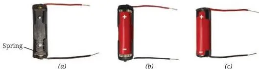
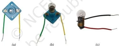

Chapter 3 opens with Nihal’s class preparing a presentation on the uses of electricity before their school trip to the Bhakra Nangal Dam. Their list groups everyday uses under cooking, lighting, transportation, heating and cooling, and other uses (NCERT, p. 23).
The chapter then narrows the focus deliberately: instead of studying mains electricity, it builds every idea around a torchlight, so you learn from a portable, cell-powered device you can handle safely.
Follow the learning path in this order, using the NCERT page numbers as your map:
- Uses of electricity and safety (pp. 23–24): how the chapter begins with everyday uses, and the caution that experiments must use only cells or batteries — never the mains supply.
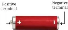
- Torch and electric cell (pp. 24–25): a torch opens to reveal two or more cells; every cell has a positive and a negative terminal.
- Battery and lamps (pp. 25–27): cells joined positive-to-negative form a battery; incandescent lamps use a filament, LEDs do not.
- Complete circuit and current direction (p. 30): a lamp glows only when a complete conducting path exists; current is taken to flow from positive to negative.
- Switch (p. 32): a switch closes the circuit in its ON position and breaks it in its OFF position.
- Circuit diagrams (pp. 33–34): every component gets a standard symbol, so circuits can be drawn on paper instead of photographed.
- Conductors, insulators, AC and DC (pp. 35–36): metals conduct electricity; plastic, rubber and ceramics protect us; batteries give DC while wall sockets give AC.
- Summary, exercises and projects (pp. 37–40): ‘In a Nutshell’ revises the chapter, ‘Let Us Enhance Our Learning’ tests it, and the exploratory projects extend it to solar panels and daily life.
The ‘Let us…’ activities and the idea each one builds
The chapter teaches through a sequence of short ‘Let us…’ activities, each one built to leave a single idea behind. Work through them in order, and the concepts below will stick.
| Activity | NCERT page | The idea it builds |
|---|---|---|
| 3.1 Let us explore | p. 24 | A torch holds cells, a lamp and a switch; the lamp glows in only one switch position. |
| 3.2 Let us observe | p. 25 | An electric cell has two terminals: the metal cap is positive, the metal disc is negative. |
| 3.3 Let us experiment | p. 25 | Cells must be joined positive-to-negative; two or more cells in that order form a battery. |
| 3.4 Let us observe | p. 26 | An incandescent lamp glows through its filament, held by two thicker wires that form its two terminals. |
| 3.5 Let us observe | p. 27 | An LED has no filament; its longer wire is positive and its shorter wire is negative. |
| 3.6 Let us construct | pp. 28–29 | A lamp glows only when the circuit gives a complete path from one cell terminal to the other. The book frames this as prediction versus observation in Table 3.1. |
| 3.7 Let us experiment | pp. 30–31 | Current passes through an LED in one direction only; it glows when its longer wire connects to the positive terminal. |
| 3.8 Let us construct | p. 32 | A working switch can be built from a safety pin, two drawing pins and a piece of cardboard. |
| 3.9 Let us test | p. 32 | ON means a closed circuit with current flowing; OFF means an open circuit with a gap. |
| 3.10 Let us draw | p. 33 | Real circuits can be redrawn neatly using the standard electrical symbols. |
| 3.11 Let us identify | pp. 35–36 | A conduction tester separates conductors (lamp glows) from insulators (lamp stays off). |
Two cautions bracket these activities. Never experiment with the power supply at home or school — even portable generators are dangerous. Use only cells or batteries, like those in torches, wall clocks and remotes (NCERT, p. 24).
The body is a conductor, so the same activities teach safety: never touch switches or plugs with wet hands, and avoid electrical devices in wet areas (NCERT, p. 36).
Key ideas in the chapter
These six ideas are the backbone of the chapter, and each one is tied to the NCERT page where the book builds it. Read them in order.
Cell and battery (p. 25)
The cell is the energy source everything else depends on, so the book examines it first. An electric cell is a portable source of electrical energy with two terminals: the protruding metal cap is the positive terminal and the flat metal disc is the negative terminal, with ‘+’ and ‘−’ signs printed on the body.
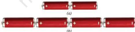
Two or more cells connected positive-to-negative form a battery. Connecting more cells provides energy to the circuit for a longer time and/or more energy. The book notes that the term ‘battery’ is also used for the single cell that powers a mobile phone (NCERT, p. 26).
Filament lamp and LED (pp. 26–27)
Torches use one of two families of lamps, and telling them apart is the first skill of the chapter. An incandescent lamp has a thin filament inside its glass bulb.
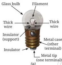
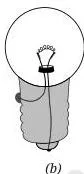
The filament is held by two thicker support wires — one reaches the metal case at the base, the other the metal tip at the centre — and these form the lamp’s two terminals, fixed so they do not touch. When current passes through the filament, it gets hot and glows.
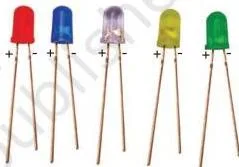
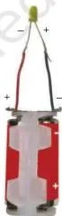
An LED (Light Emitting Diode) is different. It has no filament, and its two terminals are easy to recognise because one wire is longer: the longer wire is the positive terminal and the shorter wire is the negative terminal.
Current passes through an LED in one direction only, so it glows only when its longer wire connects to the positive side of the battery and its shorter wire to the negative side (NCERT, pp. 30–31).
Worked prediction to try: take a fresh cell, a switch, an incandescent lamp and an LED, and connect all four in one loop. First connect the LED’s longer wire to the cell’s negative terminal and the shorter wire to the positive terminal, then close the switch.
Predict the result: the incandescent lamp glows, because it does not care about polarity; the LED stays dark, because current is blocked in that direction. Now swap the two LED wires so the longer one receives the positive terminal. Both lamps glow — provided the switch is ON and every connection is tight.
A complete circuit and current direction (p. 30)
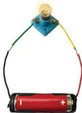
The most important idea in the chapter is that a lamp glows only when a complete path exists. An electrical circuit is formed when one terminal of the lamp connects to one terminal of the cell, and the lamp’s other terminal connects to the cell’s other terminal through wires — a complete path for electric current.
The lamp glows only when current passes through it.
The direction of electric current is taken to be from the positive to the negative terminal of the cell. You do not need to see charges moving: this convention fixes the direction for every reasoning question that follows.
Switch: closed and open circuit (p. 32)
A switch gives you control over whether the path is complete, which is exactly why the torch lamp glows in one switch position and not the other. A switch is a simple device that either completes or breaks a circuit.
When its metal contact bridges the two ends, the circuit is closed (ON) and current flows; when a gap remains, the circuit is open (OFF) and current stops. A switch can be placed anywhere in a circuit.
Worked switch combination. Suppose a circuit has two lamps, X and Y, each in its own branch with its own switch — switch A controls lamp X, switch B controls lamp Y — and both branches are joined across one battery.
| Switch A | Switch B | Lamp X | Lamp Y |
|---|---|---|---|
| ON | ON | Glows | Glows |
| ON | OFF | Glows | Does not glow |
| OFF | ON | Does not glow | Glows |
| OFF | OFF | Does not glow | Does not glow |
The rule behind every row: a lamp glows only when its branch forms a closed path from the battery’s positive terminal to its negative terminal.
Circuit diagrams and symbols (pp. 33–34)
Photographing circuits is clumsy, so the chapter teaches a compact symbol language. A circuit diagram is a representation of an electrical circuit using standard symbols. In the symbol for a cell, the long line represents the positive terminal and the short line the negative terminal.
In the symbol for an LED, the triangle points in the direction in which current can flow, and the two arrows show that it emits light. International bodies such as the IEC, ANSI and IEEE set these standard symbols so that people across the world read the same diagram the same way (NCERT, p. 34).
Conductors, insulators and safety (pp. 35–36)
The conduction-tester activity answers two practical questions: why wires are made of metal, and why they are wrapped in plastic. Conductors are materials through which electric current can flow easily — metals are conductors, which is why they are used for wires.
Insulators, or poor conductors, are materials through which current cannot pass — plastic, rubber and ceramics — which is why they cover wires, plug tops and switches to protect people from electric shocks.
The safety list the book builds is short and exam-relevant:
- Never perform experiments with the power supply at home or school; even portable generators are dangerous. Use only cells or batteries (NCERT, p. 24).
- The body is a conductor of electricity; current passing through the body may cause severe injury or even death (NCERT, p. 36).
- Never touch switches or plugs with wet hands, and do not use electrical devices in wet areas (NCERT, p. 36).
- Do not handle equipment with damaged insulation or broken plugs (NCERT, p. 36).
Batteries give Direct Current (DC), usually powering small devices; wall sockets deliver Alternating Current (AC) from power plants, which can run larger appliances (NCERT, p. 36).
Reading the diagrams: what the NCERT figures show
The figures carry most of the teaching in this chapter. Here is what to look for in each one, in the order the book presents them.
The torch, the cell and the battery (Figs 3.1–3.3)
Fig. 3.1 (p. 24): the switch is the only moving part on a torch. Sliding it one way makes the lamp glow; sliding it back stops the light.
Fig. 3.2 (p. 25): the protruding metal cap is the positive terminal; the flat metal disc is the negative terminal. The ‘+’ and ‘−’ marks are printed on the body.
Fig. 3.3 (p. 25): the positive terminal of one cell connects to the negative terminal of the next — the order that makes a torch glow. Such a combination of two or more cells is a battery.
How the two lamps differ (Figs 3.4–3.6)
Fig. 3.4 (p. 26): find the thin filament inside the glass bulb. Two thicker wires support it; one runs to the metal case at the base and the other to the metal tip in the centre. These are the lamp’s two terminals, fixed so they never touch.
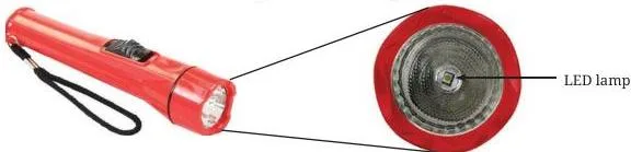
Fig. 3.5 (p. 27): an LED lamp for a torch has no filament — compare it with Fig. 3.4 and the difference is obvious at once.
Fig. 3.6 (p. 27): LEDs of different colours, each with two wires of unequal length — the longer wire is the positive terminal, the shorter the negative.
The complete circuit and the LED rule (Figs 3.9–3.10)
Fig. 3.9 (p. 30): the cell and lamp are joined so current has a complete route from one cell terminal, through the lamp, back to the other terminal. That complete loop is an electrical circuit.
Fig. 3.10 (p. 31): the four stages of connecting an LED. It glows only in the connection where its longer wire receives the positive side of the battery; swapping the wires stops it.
The switch in action (Figs 3.11–3.12)
Fig. 3.11 (p. 32): the homemade switch — a safety pin pivoting on one drawing pin. In the OFF position the free end is lifted away; in the ON position it touches the second drawing pin.
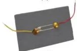
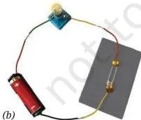
Fig. 3.12 (p. 32): the same switch placed in a real circuit. The OFF position leaves a gap, so the lamp stays dark; the ON position bridges the gap, so the lamp glows.
Symbols and circuit diagrams (Figs 3.13–3.14)
Fig. 3.13 (p. 34): in the symbol for a cell, the long line means positive and the short line negative. In the LED symbol, the triangle points in the direction current can flow and the arrows show light emission.
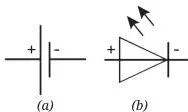
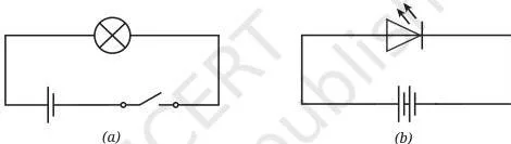
Fig. 3.14 (p. 34): the same circuit drawn with symbols, once with an incandescent lamp and once with an LED — the neat result you should get from Activity 3.10.
The conduction tester (Fig. 3.15)
Fig. 3.15 (p. 35): a cell, a lamp and two free wire ends. Touch the ends together and the lamp glows if the tester works; place a material between the ends and the lamp glows only if that material conducts electricity.
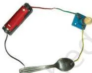
As you move through the figures, one question answers most of them: is the path from the cell’s positive terminal to its negative terminal complete?
Key terms and definitions in Chapter 3
Scan this glossary the night before a test. Every definition is written in plain words and tied to the NCERT page where the book introduces it.
| Term | Meaning | NCERT page |
|---|---|---|
| Electric cell | A portable source of electrical energy with two terminals. | p. 25 |
| Positive terminal | The terminal of a cell marked ‘+’; on a cell it is the protruding metal cap. | p. 25 |
| Negative terminal | The terminal of a cell marked ‘−’; on a cell it is the flat metal disc. | p. 25 |
| Battery | Two or more cells connected positive-to-negative; the term is also used for a single cell. | pp. 25–26 |
| Filament | The thin wire inside an incandescent lamp that gets hot and glows when current passes. | p. 26 |
| Incandescent lamp | A lamp that produces light through a glowing filament; its polarity does not matter. | p. 26 |
| LED (Light Emitting Diode) | A lamp with no filament; its longer wire is positive, its shorter wire negative, and current passes through it in one direction only. | p. 27 |
| Electrical circuit | A complete path through which electric current flows from a cell through a lamp and back. | p. 30 |
| Direction of current | In a closed circuit, taken to be from the positive to the negative terminal of the cell. | p. 30 |
| Switch | A simple device that completes (ON) or breaks (OFF) a circuit. | p. 32 |
| Closed circuit | The ON state in which the path is complete and current flows. | p. 32 |
| Open circuit | The OFF state in which a gap in the path stops the current. | p. 32 |
| Circuit diagram | A representation of an electrical circuit using standard symbols. | p. 33 |
| Conductor | A material through which electric current can flow easily; metals are conductors. | p. 35 |
| Insulator | A material through which current cannot pass; plastic, rubber and ceramics are insulators. | p. 35 |
Common mistakes in this chapter (and how to avoid them)
This chapter trips students in the same few places every year — usually because a circuit looks complete when it is not, or because a component is fussier than it appears. The mistakes below come straight from the chapter’s own exercises, so fixing them is exactly the revision the book expects.
| Mistake | Correct rule | How to check your answer |
|---|---|---|
| Thinking the switch is the source of current (Exercise 1, p. 37) | The cell is the source of electrical energy; the switch only completes or breaks the circuit (p. 32). | Statement (i) in Exercise 1 is the incorrect statement. |
| Connecting an LED the wrong way round (pp. 30–31) | Current passes through an LED in one direction only; its longer wire must go to the positive terminal. | Reverse the wires: if the LED stops glowing, your first direction was correct. |
| Leaving the plastic covering on wire ends (Exercise 4, p. 38) | The plastic covering is an insulator; about 1 cm must be removed from each end to expose the metal (p. 28). | With a conduction tester, touch the bare ends together — the lamp must glow. |
| Expecting a fused lamp to still pass current (p. 30) | A fused lamp has a broken filament, so the path is incomplete and current stops. | Replace the lamp with a known working one and observe the circuit. |
| Treating insulators as unimportant (p. 36) | Insulators protect people from shocks, and the body is a conductor, so the covering is what keeps you safe. | If the lamp stays off while testing a material, that material is an insulator doing its job. |
Troubleshooting a lamp that will not glow (Exercise 7, p. 38)
Vidyut’s circuit in Fig. 3.19 does not glow even after the switch is closed. Work through the circuit one suspect at a time.
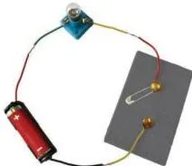
- Dead or wrongly placed cell: fit a fresh cell and check that both terminals make contact.
- Loose or covered wire: tighten every joint; strip about 1 cm of plastic from each wire end so bare metal touches bare metal.
- Open switch: make sure the switch is actually closed, with its contact bridging the two terminals.
- Fused lamp: a broken filament leaves the path incomplete; try another lamp (NCERT, p. 30).
This fault-finding habit — check the source, then the connections, then the switch, then the lamp — is the same reasoning Exercise 10 wants when you design a test to find working cells.
What the end-of-chapter questions expect of you
The exercises in ‘Let Us Enhance Our Learning’ (pp. 37–39) are qualitative like the chapter itself: they test reasoning, prediction and diagram skills, not arithmetic. Map your revision to the skill each question targets.
| Exercise | Skill it tests | What a full answer must include |
|---|---|---|
| 1. Choose the incorrect statement | Recognising what a switch really does | Statement (i) is incorrect: the switch is not the source of current — the cell is. |
| 2. Fig. 3.16 — material between A and B | Predicting conductors and insulators | The lamp will not glow when the material is an insulator, because current cannot pass through it. |
| 3. Fig. 3.17 — broken filament | Applying the complete-path idea | A broken filament breaks the path, so the current stops and the other lamp does not glow; justify using the complete-path idea. |
| 4. Insulator left on wire ends | Explaining why insulation blocks current | The plastic covering is an insulator, so the circuit cannot be completed; the ends must be stripped. |
| 5. Draw a torch circuit diagram | Drawing with standard symbols | Use the Table 3.2 symbols for cell/battery, switch and lamp, arranged in one closed loop. |
| 6. Fig. 3.18 — S₁ and S₂ combinations | Predicting lamps from switch positions | For each ON/OFF pair, decide which branches form a closed path from positive to negative — apply the switch-combination table above. |
| 7. Fig. 3.19 — Vidyut’s unlit lamp | Troubleshooting a faulty circuit | List possible faults (dead cell, loose wire, open switch, fused lamp, covered wire) and a way to test each. |
| 8. Fig. 3.20 — lamp/LED cases | Applying polarity and complete-path rules | Check each case twice: is the path complete, and is the LED the right way round (longer wire to positive)? |
| 9. Identify battery terminals without labels | Designing a method | Connect an LED to the battery; when it glows, the wire touching the LED’s longer wire is the positive terminal. |
| 10. Find the working cells | Designing a fair test | List the items (cell holder, wires, known good lamp), then test each cell one at a time and note which make the lamp glow. |
| 11. Fig. 3.21 — Tanya’s LED circuit | Applying LED polarity in a series circuit | Check which way the LED is connected; redraw the wires so its longer wire goes to the positive side of the two-cell battery. |
Two exercises ask you to read figures directly, so practise on them here. Fig. 3.16 is the conduction-tester idea from Activity 3.11: its two free ends are labelled A and B.
When a material is connected between A and B, the lamp glows only if that material is a conductor — so the lamp stays dark when an insulator such as plastic, rubber, wood or glass is placed between the ends.
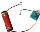
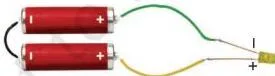
Fig. 3.21 shows Tanya’s LED, which needs two cells in series. The LED glows only when its longer wire connects towards the positive side of the two-cell battery; if the wires connect the longer wire to the negative side, the LED stays dark and the connections must be redrawn.
Revision note: the chapter is entirely qualitative — there are no formulas or calculations — so the questions reward clear reasoning, careful prediction and clean diagrams, not arithmetic.
Syllabus note: textbook contents and the examinable syllabus are not always identical — check the current official syllabus on cbse.gov.in before you decide what to revise.
Quick revision summary (from ‘In a Nutshell’)
NCERT closes the chapter with a printed summary called ‘In a Nutshell’ on page 37. Its points, regrouped for last-minute revision, are these:
- Cells and batteries: an electric cell is a portable source of electrical energy with a positive and a negative terminal. Two or more cells joined positive-to-negative form a battery.
- Incandescent lamp: a thin filament inside the glass bulb gets hot and glows when current passes through it.
- LED: no filament; the longer wire is positive and the shorter wire negative. Current flows through it in one direction only, so it lights only when its longer wire connects to positive and its shorter wire to negative.
- Circuit and current direction: an electrical circuit gives a complete path for current; the direction of current is taken from the positive to the negative terminal of the cell.
- Switch: a switch completes (ON / closed circuit) or breaks (OFF / open circuit) the circuit.
- Circuit diagram: a representation of an electrical circuit using standard symbols.
- Conductors and insulators: materials through which current flows easily are only a conductor when they glow; wrong — materials that let current flow easily are conductors, and materials that block it are insulators.
Where Chapter 3 fits in Class 7 Science
Chapter 3 takes an idea from Grade 6 ‘Nature’s Treasures’ — that electricity is generated by windmills, solar panels, falling water, natural gas and coal — and makes it hands-on: the cell, the wire and the bulb become objects you can test yourself (NCERT, p. 23).
For the rest of the year, keep the Class 7 Science book page open as your map of Curiosity, and use the Class 7 hub to jump between subjects. The chapters that follow — such as Exploring and The World of Metals — are all linked from the CBSE notes hub.
Sources and data verification
This listing is maintained for the 2026-27 academic session using the NCERT textbook information available to us. NCERT remains the authority for confirming the latest edition.
- The figures, page numbers and chapter content on this page describe the NCERT Class 7 Science textbook Curiosity, Chapter 3, pages 23–40, published by NCERT.
- This page covers Chapter 3 only. Other chapters of Curiosity have their own pages on this site.
- NCERT settles textbook editions and PDFs; CBSE settles the curriculum, syllabus and examinations. The official chapter file is on ncert.nic.in, and the current examination syllabus is published by CBSE on cbse.gov.in.
- This page is an independent student guide to the official textbook and is not a publication of CBSE or NCERT.
| What the chapter holds | Count | Where it is used |
|---|---|---|
| Printed pages | 18 | |
| Sections in the chapter | 10 | |
| Figures with NCERT captions | 32 | |
| Tables | 3 | |
| Activities | 1 | |
| Official NCERT PDF | Download the chapter PDF | the chapter exactly as NCERT publishes it |
Frequently asked questions about this chapter
Why does a torch lamp glow in one switch position and not in the other?
Because the switch has two positions: ON and OFF. In the ON position the switch closes the circuit — the safety pin bridges the two drawing pins — so current flows from the cell’s positive terminal through the filament and the lamp glows.
In the OFF position the switch leaves an air gap in the path, so no current flows and the lamp stays dark (NCERT, p. 32).
Why does an LED only glow when connected in one direction?
Because current can pass through an LED in one direction only. Its longer wire is the positive terminal and the shorter wire is the negative terminal, so it glows only when the longer wire connects to the positive terminal of the battery and the shorter wire to the negative terminal. Reverse the connections and the current is blocked (NCERT, pp. 30–31).
Is the switch the source of electric current in a circuit?
No. The electric cell is the source of electrical energy; the switch is only a device that completes or breaks the circuit (NCERT, p. 32). Exercise 1 of the chapter asks you to identify the incorrect statement — the wrong one is the claim that a switch is the source of current (NCERT, p. 37).
What is the difference between an electric cell and a battery?
A single electric cell is a portable source of electrical energy with a positive and a negative terminal. A battery is made by connecting two or more cells together, positive terminal to negative terminal (NCERT, p. 25). The chapter also notes that the word ‘battery’ is commonly used for a single cell too, as in mobile phones (NCERT, p. 26).
Why are electric wires covered with plastic or rubber?
Because plastic and rubber are insulators — electric current cannot pass through them (NCERT, p. 35). The covering keeps the current inside the wire and stops it from reaching you, which matters because the human body is a conductor and current through the body can cause severe injury (NCERT, p. 36).
What is the difference between electricity from a battery and electricity from a wall socket?
Batteries give Direct Current (DC), which usually powers small devices like torches, clocks and remotes. Wall sockets receive Alternating Current (AC) from power plants, which can run larger appliances like fans, refrigerators and geysers (NCERT, p. 36). Never experiment with mains or socket electricity — the chapter allows experiments only with cells and batteries (NCERT, p. 24).
Reference: NCERT Class 7 Science (Curiosity) textbook, Chapter 3, official edition on ncert.nic.in.
Explore Class 7 Science Books
Related chapters: