
Ray Optics and Optical Instruments Class 12 is Chapter 9 of NCERT Physics Part II, the opening chapter of the book. It explains reflection, refraction and dispersion with the ray model of light, then builds microscopes and telescopes on those two laws. This page follows the NCERT 2026-27 reprint and carries the official PDF below.
Past the download you will find a section-by-section map with NCERT page numbers, plain-language explanations of every idea, a walkthrough of the key diagrams, the mistakes that cost marks, and a formula sheet for the night before the exam.
Download the Ray Optics and Optical Instruments Class 12 PDF
Download the official NCERT Class 12 Physics Chapter 9 Ray Optics and Optical Instruments PDF from ncert.nic.in, the Council’s own portal for current textbooks, so you always work from the printed edition issued for your class rather than a photocopy or an old version.
Chapter at a glance: what is inside the file
Ray Optics and Optical Instruments opens the book’s study of how light forms images. It runs from the two basic laws — reflection and Snell’s law — through mirrors, lenses, prisms and total internal reflection, and ends with the microscope and telescope that use all of it.
The table below shows exactly how much the chapter holds, rendered from the official NCERT text.
| What the chapter holds | Count | Where it is used |
|---|---|---|
| Printed pages | 34 | |
| Sections in the chapter | 17 | |
| Figures with NCERT captions | 29 | |
| Tables | 1 | |
| Worked examples | 6 | solved step by step in our NCERT Solutions |
| Exercise questions | 31 | answered in our NCERT Solutions |
| Official NCERT PDF | Download the chapter PDF | the chapter exactly as NCERT publishes it |
What this chapter covers, section by section
The chapter moves in one direction: reflection first, refraction second, and then the instruments that combine both. Follow the table below with a finger on your own book.
| Section | What it covers | NCERT page |
|---|---|---|
| 9.1 Introduction | The ray model of light, its visible range and speed | 221 |
| 9.2 Reflection by spherical mirrors | Sign convention, focal length \( f = R/2 \), mirror equation and magnification | 222–226 |
| 9.3 Refraction | Snell’s law, optical density, lateral shift, apparent depth | 228–229 |
| 9.4 Total internal reflection | Critical angle, Table 9.1, prisms, optical fibres | 229–232 |
| 9.5 Refraction at spherical surfaces and by lenses | Single spherical surface, lens maker’s formula, thin lens formula, power, combination of lenses | 232–238 |
| 9.6 Refraction through a prism | Deviation, \( r_1 + r_2 = A \), minimum deviation | 239–240 |
| 9.7 Optical instruments | Simple and compound microscope, telescope, reflecting (Cassegrain) telescope | 240–246 |
| Summary and Points to Ponder | Formula recap and the fine points that trap students | 246–248 |
| Exercises | Problems running through every idea in the chapter | 249–253 |
The core ideas explained
Each idea below is what the chapter actually teaches, in the order the book teaches it, with the NCERT page so you can follow along. Read them in order — each one leans on the last.
The ray model and why it works
The chapter treats light as a ray — a straight line of travel. That is not a contradiction of the wave model: visible light has a wavelength of about 400 nm to 750 nm, tiny against the size of everyday objects (NCERT, p. 221).
When the wavelength is that small, a wave can be drawn as a straight path, and a bundle of rays is a beam.
The book uses the ray picture to study reflection, refraction and dispersion, and the same two laws do all the work (NCERT, p. 221). The speed of light in vacuum is \( c = 3 \times 10^{8}\ \text{m s}^{-1} \), the fastest speed in nature.
The Cartesian sign convention
Every formula in this chapter works for every mirror and lens only because of one rule: the Cartesian sign convention. Get a sign wrong and even a perfectly done calculation gives the wrong answer.
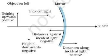
- All distances are measured from the pole of the mirror or the optical centre of the lens.
- Distances in the direction of the incident light are positive; against it, negative. This makes a real object’s distance \( u \) negative, because you travel against the incident light to reach it.
- Heights measured upward are positive; downward, negative (NCERT, p. 222).
This single convention is what lets one mirror formula and one lens formula handle every case (NCERT, p. 222).
Spherical mirrors: focus, mirror equation, magnification
A concave mirror gathers light; a convex mirror spreads it. Both obey the same two laws of reflection at every point, so both are described by the same equation once the signs are fixed.
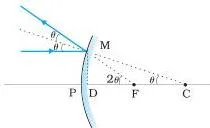
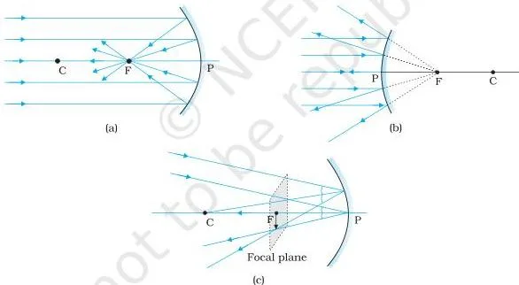
For rays close to the principal axis (paraxial rays), a parallel beam converges at the principal focus F of a concave mirror and appears to diverge from F for a convex one; the distance PF is the focal length \( f \) (NCERT, p. 223).
A small-angle tangent proof gives \( f = R/2 \), where R is the radius of curvature (NCERT, p. 224), using the geometry of Fig. 9.4.
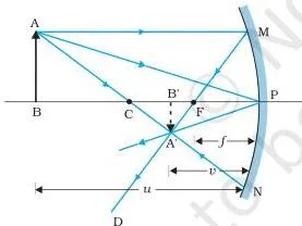
The mirror equation \( \frac{1}{v} + \frac{1}{u} = \frac{1}{f} \) and the magnification \( m = \frac{h’}{h} = -\frac{v}{u} \) are derived from the similar triangles of Fig. 9.5 (NCERT, pp. 225–226).
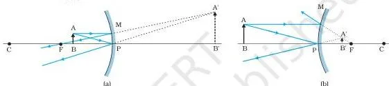
The sign of \( v \) tells you the nature of the image: a negative \( v \) means the image is in front of the mirror (real and inverted), a positive \( v \) means behind it (virtual and erect).
Examples 9.1–9.4 in the book show the ideas in action — covering half a mirror (the image stays whole, just dimmer), a phone lying along the axis (distorted because magnification is not uniform), an object placed in the two image regions, and the side-view mirror of a car (a jogger’s image appears to speed up as they approach).
Worked example: the sign convention decides real or virtual
A concave mirror has a focal length of 10 cm. Where is the image, and what is its nature, when the object is (i) 30 cm and (ii) 6 cm in front of it?
Step 1: A concave mirror has a negative focal length, so \( f = -10\ \text{cm} \).
A real object lies against the incident light, so \( u \) is negative in both cases.
Step 2 (case i): \( u = -30\ \text{cm} \).
Use \( \frac{1}{v} + \frac{1}{u} = \frac{1}{f} \):
\[ \frac{1}{v} + \frac{1}{-30} = \frac{1}{-10} \qquad \Rightarrow \qquad \frac{1}{v} = -\frac{1}{10} + \frac{1}{30} = -\frac{2}{30} \]
\[ v = -15\ \text{cm}, \qquad m = -\frac{v}{u} = -\frac{(-15)}{(-30)} = -0.5 \]
Final answer (i): a real, inverted, diminished image, 15 cm in front of the mirror.
Step 3 (case ii): \( u = -6\ \text{cm} \), object between pole and focus:
\[ \frac{1}{v} + \frac{1}{-6} = \frac{1}{-10} \qquad \Rightarrow \qquad \frac{1}{v} = -\frac{1}{10} + \frac{1}{6} = \frac{2}{30} \]
\[ v = +15\ \text{cm}, \qquad m = -\frac{v}{u} = -\frac{15}{(-6)} = +2.5 \]
Final answer (ii): a virtual, erect, magnified image, 15 cm behind the mirror.
Only the object position changed between the two cases — and the sign of \( v \) decided everything. The object distance \( u \) stayed negative both times because a real object always lies against the incident light (NCERT, p. 225).
Which rays to draw in a ray diagram
You only need two rays to locate an image. Which two you pick depends on what you are trying to show (NCERT, p. 224):
- Ray parallel to the principal axis — reflects (or refracts) through the focus. Always available and the simplest to draw.
- Ray through the centre of curvature C (or aimed at it, for a convex mirror) — retraces its path. Best for fixing the final image position.
- Ray through (or toward) the focus — emerges parallel to the axis. Useful when the object sits between P and F.
- Ray that strikes the pole — obeys the ordinary laws of reflection. Good when the other rays would meet far off the page.
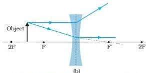
For a convex mirror or a concave lens, draw the same rays and extend them backwards — the virtual image lies where the extended rays meet. A ray through the optical centre of a lens, which passes undeviated, is the usual check on the first two (Fig. 9.17, NCERT, p. 235).
Refraction: Snell’s law and its consequences
Light changes direction when it enters another transparent medium. Snell’s law gives the amount of bending, and every later idea in the chapter builds on it.
Snell’s law: \( \frac{\sin i}{\sin r} = n_{21} \), a constant for any pair of media (it also depends on wavelength) and independent of the angle of incidence (NCERT, p. 228). When \( n_{21} \gt 1 \), the ray bends toward the normal and medium 2 is optically denser.
Optical density is not mass density: turpentine has a lower mass density than water but a higher optical density (NCERT, p. 229). Reversing the direction simply inverts the index: \( n_{12} = 1/n_{21} \).
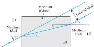
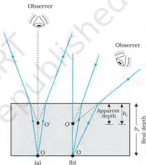
Two results follow immediately. A ray through a parallel-sided slab emerges parallel to itself but laterally shifted (Fig. 9.9), and the bottom of a tank appears raised — the apparent depth equals the real depth divided by the refractive index (Fig. 9.10, NCERT, p. 229).
Total internal reflection: when light cannot escape
When light goes from a denser to a rarer medium it bends away from the normal. Past a certain angle of incidence it cannot refract at all and is reflected completely — this is total internal reflection (NCERT, p. 230).
The critical angle is the angle of incidence for which the refracted ray grazes the surface with \( r = 90^\circ \). From Snell’s law, \( \sin i_c = n_{21} \) (NCERT, p. 230). Table 9.1 gives the critical angles with respect to air: water 48.75°, crown glass 41.14°, dense flint glass 37.31°, diamond 24.41° (p. 230) — the higher the refractive index, the smaller the critical angle.
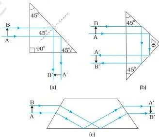
Applications in the chapter: prisms that bend light by 90° or 180° and invert images without changing size (Fig. 9.13), optical fibres, and the mirage (NCERT, p. 246). A fibre’s core has a higher refractive index than its cladding, so light suffers successive total internal reflections along the whole length (Fig. 9.14); silica fibres transmit more than 95% of the light over 1 km (NCERT, p. 232).
Lenses: from one spherical surface to the lens maker’s formula
A lens is two spherical refracting surfaces in a row. The image from the first surface acts as the object for the second, and adding the two results gives every lens formula in the chapter (NCERT, p. 234).
For a single spherical surface separating media of index \( n_1 \) and \( n_2 \): \( \frac{n_2}{v} – \frac{n_1}{u} = \frac{n_2 – n_1}{R} \) (NCERT, p. 233). Applied at both surfaces of a thin lens this gives the lens maker’s formula \( \frac{1}{f} = (n_{21} – 1)\left( \frac{1}{R_1} – \frac{1}{R_2} \right) \) and the thin lens formula \( \frac{1}{v} – \frac{1}{u} = \frac{1}{f} \) (NCERT, pp. 234–235).
Note the lens formula has a minus where the mirror equation has a plus — the two are not interchangeable.
Power \( P = 1/f \) is measured in dioptres, \( 1\ \text{D} = 1\ \text{m}^{-1} \), positive for a converging lens and negative for a diverging one (NCERT, p. 236). For thin lenses in contact, \( \frac{1}{f} = \frac{1}{f_1} + \frac{1}{f_2} + \dots \), powers add algebraically, and the total magnification is the product \( m = m_1 m_2 \dots \) (NCERT, p. 238).
Example 9.6 shows the striking case where a lens vanishes because the surrounding liquid has the same refractive index, making \( 1/f = 0 \) and \( f \to \infty \); Example 9.7 shows the same glass lens has a much longer focal length in water than in air.
The prism: deviation and minimum deviation
A prism bends the ray twice, once at each face, and the two bendings combine into a single angle of deviation (NCERT, p. 239).
The geometry gives \( r_1 + r_2 = A \) (the two internal refractions share the prism angle) and \( \delta = i + e – A \). The deviation curve of Fig. 9.22 is symmetric about its minimum: at minimum deviation \( D_m \), the ray inside the prism is parallel to the base, so \( i = e \) and \( r_1 = r_2 = A/2 \), giving \[ n_{21} = \frac{\sin[(A + D_m)/2]}{\sin(A/2)} \]
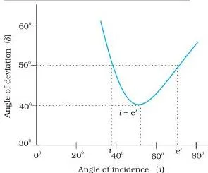
This is how the refractive index of a prism is measured (NCERT, p. 240). For a thin prism the deviation is small, and \( D_m \approx (n_{21} – 1)A \).
Microscope and telescope: what each magnifies
A microscope enlarges a small near object; a telescope enlarges the angle a distant object subtends. The difference in objective design is the whole story (NCERT, p. 240).
Simple microscope: \( m = 1 + D/f \) when the image is at the near point \( D \approx 25\ \text{cm} \), and \( m = D/f \) when the image is at infinity (NCERT, pp. 241–242). To get six times magnification you need \( f = 5\ \text{cm} \).
Compound microscope: the objective forms a real, inverted, magnified image and the eyepiece magnifies it again; \( m \approx (L/f_o)(D/f_e) \), so both focal lengths should be short (NCERT, p. 243). The book works out \( m = 250 \) for \( f_o = 1\ \text{cm} \), \( f_e = 2\ \text{cm} \) and a tube length of 20 cm.
Telescope: \( m = f_o/f_e \), with a long-focus objective and a short-focus eyepiece; the tube length is \( f_o + f_e \) (NCERT, p. 244). Reflecting telescopes replace the lens objective with a mirror — there is no chromatic aberration, and a mirror is far easier to support.
The Cassegrain design folds the focused light back through a hole in the primary mirror, giving a long focal length in a short tube (Fig. 9.26, NCERT, pp. 245–246).
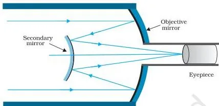
Figure walkthrough: what the diagrams actually show
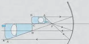
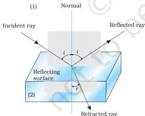
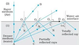
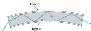
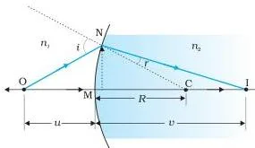
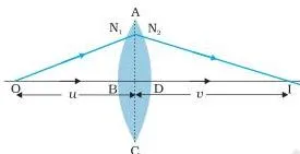
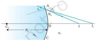
These six diagrams carry the reasoning of the chapter. Each one is explained below so you can read it in your own book; others (9.3, 9.6, 9.8–9.10, 9.13, 9.17, 9.22, 9.26) are referenced by number in the sections above.
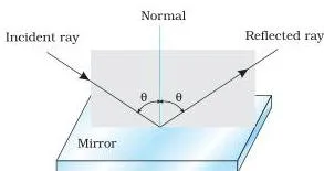
This is the rule that makes every formula in the chapter work. The arrow on NCERT page 222 points in the direction of the incident light; any distance you measure in that direction gets a positive sign, any distance against it gets a negative sign, and heights are positive upward.
Memorise the three rules and the signs of \( u \) and \( f \) follow automatically.
Two rays leave the tip A of the object: one parallel to the axis reflecting through F, and one through C retracing its path. Where the reflected rays cross is the image A’. The similar triangles in this drawing are exactly what the chapter uses to derive \( \frac{1}{v} + \frac{1}{u} = \frac{1}{f} \) (NCERT, p. 225).
The image here is real and inverted because the reflected rays actually meet in front of the mirror.
Rays from the point A in water strike the surface at increasing angles. Ray AO₁ refracts out with \( r \gt i \); ray AO₃ grazes the surface with \( r = 90^\circ \) — that angle of incidence is the critical angle; ray AO₄ cannot escape and reflects back into the water.
The figure shows why \( \sin i_c = n_{21} \): refraction is only possible while the refracted ray can still emerge, and the grazing ray is the last one that can (NCERT, p. 230).
The fibre is drawn as a long pipe with a ray bouncing between its walls. Each bounce is a total internal reflection, so no light leaks out — which is why more than 95% of the light survives a 1 km length of silica fibre (NCERT, p. 232).
The core has a higher refractive index than the cladding, so the ray stays inside the core for the whole journey, even if the fibre is bent.
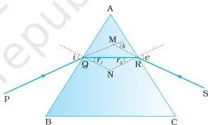
The ray PQ enters the prism, refracts inside with angle \( r_1 \), and exits at the second face with emergence angle \( e \). The quadrilateral AQNR has two right angles, so \( \angle A + \angle QNR = 180^\circ \); the triangle QNR gives \( r_1 + r_2 + \angle QNR = 180^\circ \). Comparing the two: \( r_1 + r_2 = A \) (NCERT, p. 239).
That single relation unlocks everything else about prisms, including minimum deviation.
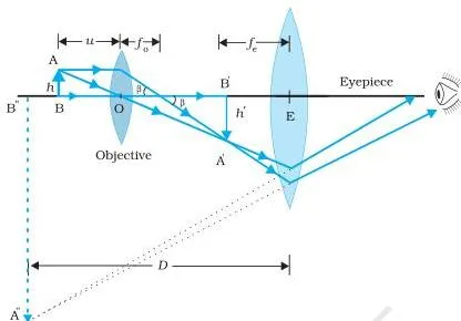
The objective lens forms a real, inverted, magnified first image of the object; that first image sits near the focal plane of the eyepiece, which then acts like a simple magnifier and enlarges it into a final virtual image.
The linear magnification of the objective is \( L/f_o \), the eyepiece contributes \( D/f_e \), and together they give \( m \approx (L/f_o)(D/f_e) \) (NCERT, p. 243).
Key definitions at a glance
The terms below are the vocabulary of the chapter. Each is the definition a student actually uses, with the unit where one exists.
| Term | Plain meaning | Unit |
|---|---|---|
| Ray and beam | A ray is the straight-line path light is taken to follow; a beam is a bundle of rays (p. 221). | — |
| Pole / optical centre | The geometric centre of a spherical mirror / lens; the origin for all distance measurements (p. 222). | — |
| Centre of curvature | The centre of the sphere of which the mirror is a part; the normal at any point passes through it (p. 222). | — |
| Principal axis | The line joining the pole and the centre of curvature of a mirror (p. 222). | — |
| Principal focus and focal length | F is where a parallel paraxial beam converges (concave) or appears to diverge from (convex); \( f \) is the distance PF, with \( f = R/2 \) (p. 223). | metre (commonly cm) |
| Real vs virtual image | Real — rays actually meet at the point; virtual — rays appear to diverge from the point when produced backwards (p. 224). | — |
| Refractive index \( n_{21} \) | The ratio \( \sin i / \sin r \) for the pair of media, fixed for the pair and the wavelength (p. 228). | dimensionless |
| Critical angle \( i_c \) | The angle of incidence (denser to rarer) for which the angle of refraction is 90°; \( \sin i_c = n_{21} \) (pp. 229–230). | degree |
| Power of a lens \( P \) | The convergence or divergence a lens gives to a parallel beam; \( P = 1/f \), positive for converging, negative for diverging (p. 236). | dioptre (D) |
| Linear magnification \( m \) | The ratio of image height to object height; for a mirror \( m = -v/u \) (pp. 225–226). | dimensionless |
| Angular magnification / magnifying power | The ratio of the angle the image subtends at the eye to the angle the object subtends without the instrument (pp. 242, 244). | dimensionless |
Mistakes students make in this chapter
The chapter’s own Points to Ponder (p. 248) and its note on optical density (p. 229) name exactly where readers go wrong. Each row below names the mistake before you make it.
| Mistake | Correct rule | How to check your answer |
|---|---|---|
| The image disappears when the screen is removed | It is still there — the rays are still converging to that image point; the screen only diffuses them so your eye can catch them (p. 248). | Put your hand or a paper at the image location and the image catches on it; think of a laser show drawing images in air. |
| Optical density equals mass density | Optical density is the ratio of the speeds of light in two media; turpentine is mass-lighter but optically denser than water (p. 229). | Compare which way the ray bends, never which liquid weighs more. |
| Object distance \( u \) is taken positive | A real object lies against the incident light, so \( u \) is always negative (p. 222). | \( u \) carries a minus sign in every substitution; if your \( v \) comes out with the wrong sign, re-check \( u \) first. |
| Mirror and lens equations use the same sign | Mirror: \( \frac{1}{v} + \frac{1}{u} = \frac{1}{f} \); lens: \( \frac{1}{v} – \frac{1}{u} = \frac{1}{f} \) (pp. 225, 235). | Write the formula you are using before substituting; a swapped sign flips the final image position. |
| A concave mirror always gives a real image | Only when the object is beyond the focus. Between pole and focus the image is virtual and erect (Example 9.3(ii), pp. 226–227). | Object at 5 cm with \( f = 7.5\ \text{cm} \) gave \( v = +15\ \text{cm} \) (virtual); at 10 cm it gave \( v = -30\ \text{cm} \) (real). |
| Linear magnification equals magnifying power of a magnifier | Linear \( m \) compares sizes; magnifying power compares angles. A magnifier gives magnification because the object can be brought closer than the near point (pp. 242, 248). | Exercises 9.22–9.24 work this exact difference step by step. |
Why the image is still there without the screen — and why a book page forms none
The rays from a point on the object are converging at the image point in space; the screen merely diffuses those converging rays so some reach your eye. That is why a laser show can draw images in mid-air with no screen at all (NCERT, p. 248).
Image formation needs regular reflection or refraction: every ray from a given point must reach the same image point. An irregular surface like a book page sends rays off in all directions, so no image forms (NCERT, p. 248). Thick lenses give coloured images through dispersion — one reason real instruments use combinations of lenses that cancel optical defects.
Exam notes: what the exercises actually test
The 31 end-of-chapter exercises are grouped below by the concept each set tests, so you can target the ideas you find hardest. Solving them is your preparation; this table is your map.
| Exercises | Concept tested |
|---|---|
| 9.1–9.2 | Mirror equation and magnification, concave and convex |
| 9.3 | Apparent depth and refractive index |
| 9.4 | Snell’s law applied across two interfaces |
| 9.5 | Total internal reflection from a submerged source |
| 9.6 | Prism minimum deviation formula |
| 9.7 | Lens maker’s formula |
| 9.8–9.9 | Lens formula with converging and diverging beams |
| 9.10 | Combination of lenses in contact |
| 9.11–9.12 | Compound microscope setup and magnifying power |
| 9.13–9.14 | Telescope magnifying power; diameter of the Moon’s image |
| 9.15 | Algebraic deductions from the mirror equation |
| 9.16 | Lateral shift through a slab |
| 9.17 | Light pipe and total internal reflection |
| 9.18–9.19 | Lens producing a sharp image on a screen |
| 9.20 | Two separated lenses |
| 9.21 | Prism with total internal reflection at one face |
| 9.22–9.25 | Magnifying glass; linear vs angular magnification |
| 9.26 | Designing a 30X compound microscope |
| 9.27–9.28 | Telescope in normal adjustment and with final image at 25 cm |
| 9.29 | Cassegrain telescope |
| 9.30–9.31 | Galvanometer mirror; liquid-lens experiment |
One honest caution: textbook contents and the examinable syllabus are not always identical. Check the current official CBSE syllabus for Class 12 Physics to see which portions of this chapter are examinable this year — this map describes the chapter, not a promise about the paper.
Quick revision: the formulas to have ready
This is the SUMMARY on NCERT pages 246–248 turned into a look-up table. Every symbol is named and every unit given.
| What it is | Formula | Symbols and units |
|---|---|---|
| Mirror equation | \( \frac{1}{v} + \frac{1}{u} = \frac{1}{f} \) | \( u \) object distance, \( v \) image distance, \( f \) focal length (m or cm, consistent); \( f = R/2 \); \( f \) negative concave, positive convex |
| Magnification (mirror) | \( m = \frac{h’}{h} = -\frac{v}{u} \) | \( h, h’ \) heights; \( m \) negative means inverted |
| Snell’s law | \( \frac{\sin i}{\sin r} = n_{21} \) | \( i, r \) angles with the normal; \( n_{21} \) fixed for the pair of media |
| Critical angle | \( \sin i_c = n_{21} \) | denser to rarer; beyond \( i_c \) no refraction is possible |
| Single spherical surface | \( \frac{n_2}{v} – \frac{n_1}{u} = \frac{n_2 – n_1}{R} \) | \( n_1, n_2 \) refractive indices; \( R \) radius of curvature, signed |
| Lens maker’s formula | \( \frac{1}{f} = (n_{21} – 1)\left( \frac{1}{R_1} – \frac{1}{R_2} \right) \) | \( n_{21} = n_2/n_1 \); \( R_1, R_2 \) signed radii of the two surfaces |
| Thin lens formula | \( \frac{1}{v} – \frac{1}{u} = \frac{1}{f} \) | \( f \) positive converging, negative diverging |
| Power of a lens | \( P = \frac{1}{f} \) | dioptre (D); \( 1\ \text{D} = 1\ \text{m}^{-1} \); plus converging, minus diverging |
| Lenses in contact | \( \frac{1}{f} = \frac{1}{f_1} + \frac{1}{f_2} + \dots \), \( P = P_1 + P_2 + \dots \), \( m = m_1 m_2 \dots \) | powers add algebraically; magnifications multiply |
| Prism | \( r_1 + r_2 = A \); \( n_{21} = \frac{\sin[(A + D_m)/2]}{\sin(A/2)} \) | \( A \) refracting angle, \( D_m \) minimum deviation; thin prism \( D_m \approx (n_{21} – 1)A \) |
| Simple microscope | \( m = 1 + \frac{D}{f} \) (near point); \( m = \frac{D}{f} \) (infinity) | \( D \approx 25\ \text{cm} \), the least distance of distinct vision |
| Compound microscope | \( m \approx \frac{L}{f_o} \times \frac{D}{f_e} \) | \( L \) tube length, \( f_o, f_e \) objective and eyepiece focal lengths |
| Telescope | \( m = \frac{f_o}{f_e} \) | tube length \( f_o + f_e \) in normal adjustment |
Related resources
For the wider Class 12 Physics picture, start at the Class 12 Physics hub, which collects the notes for every chapter. The Class 12 hub gathers all subjects on this site, and the full study-notes collection covers every class. When you move back to earlier chapters, the notes for Electrostatic Potential and Capacitance are a useful refresher.
Inside the book itself: the previous chapter, 8 (Electromagnetic Waves), closes Physics Part I, and the next chapter, 10 (Wave Optics), continues straight from this one — replacing rays with waves and explaining the phenomena (like interference and diffraction) that the ray model cannot.
Sources and data verification
Where do the facts on this page come from? The section titles, page references, figure captions and formulas come from the official NCERT Class 12 Physics Part II textbook, Chapter 9 (Ray Optics and Optical Instruments), current edition as published on ncert.nic.in. The chapter opens at NCERT printed page 220.
What this page covers: the sections, figures, worked examples and exercises of this one chapter. It does not include the CBSE syllabus, marking scheme or previous-paper analysis, which are separate documents.
Session: this page is maintained for the current session using the NCERT information available to us at the time of writing.
Which authority settles what: NCERT governs the textbook text, figures, page numbers and the official PDF; CBSE governs the examinable syllabus and the examination itself. The two are different bodies — a textbook is not the syllabus.
Reference: NCERT Class 12 Physics textbook, Chapter 9 (Ray Optics and Optical Instruments), official edition on ncert.nic.in.
FAQ: Ray Optics and Optical Instruments Class 12
What is the mirror equation and when is it valid?
The mirror equation is \( \frac{1}{v} + \frac{1}{u} = \frac{1}{f} \), where \( u \) is the object distance, \( v \) the image distance and \( f \) the focal length (NCERT, p. 225).
It is valid for all cases of reflection by a spherical mirror — concave or convex, real or virtual — provided you apply the Cartesian sign convention: \( u \) negative for a real object, \( f \) negative for a concave mirror.
Why does a convex mirror always form a diminished virtual image?
Because the reflected rays from a convex mirror never actually meet — they appear to diverge from a point behind the mirror, so the image is always virtual, erect and smaller than the object, located between the pole and the focus (Fig. 9.6b).
Exercise 9.15 derives exactly this from the mirror equation, and the side-view mirror of a car is the familiar example (Example 9.4).
What is the critical angle and why is it small for diamond?
The critical angle is the angle of incidence, going from denser to rarer, for which the angle of refraction is 90°; \( \sin i_c = n_{21} \). The larger the refractive index, the smaller the critical angle.
Diamond has \( n = 2.42 \), so \( i_c \approx 24.4^\circ \) (Table 9.1, p. 230; SUMMARY, p. 246) — that small angle is why diamond produces so many total internal reflections and sparkles the way it does.
What is the difference between linear magnification and angular magnification in a magnifying glass?
Linear magnification compares image size to object size (\( h’/h \)); angular magnification (magnifying power) compares the angle the image subtends at the eye to the angle the object subtends without the lens.
In a simple microscope the angular size of the image equals the angular size of the object, yet magnification exists because the lens lets you bring the object closer than the near point of 25 cm (NCERT, p. 242; POINTS TO PONDER, p. 248). Exercises 9.22–9.24 drill this difference.
How does a Cassegrain telescope differ from a refracting telescope?
A refracting telescope uses a large lens as its objective; a Cassegrain uses a large concave mirror (the primary) plus a convex secondary mirror that sends the focused light back through a hole in the primary (Fig. 9.26).
The mirror design has no chromatic aberration, is much lighter to support, and gives a long focal length in a short tube (NCERT, pp. 245–246).
Where can I download the official NCERT Class 12 Physics Part II PDF?
The official PDF is published by NCERT on ncert.nic.in, the Council’s website. This chapter is Chapter 9 (Ray Optics and Optical Instruments) of Physics Part II, and the link in the download section above takes you to the source so you always get the current printed edition rather than a photocopy.
Explore Class 12 Physics Books
- Previous: Electromagnetic Waves
- Next: Wave Optics
Related chapters:
- Electric Charges and Fields
- Electrostatic Potential and Capacitance
- Current Electricity